
Fisons 8000
| Objektnummer | B00011114 |
|---|---|
| ID-Nummer | 011114 |
| Objektbezeichnung | Fisons 8000 |
| Status | Archiviertes Produkt |
Produktgruppe: GC / MS
Status, Liefer- und Zahlungsbedingungen
Geräteüberprüfung
Die gebrauchten Laborgräte werden vor der Auslieferung von der Labexchange Service GmbH überprüft. Sie erhalten voll funktionsfähige Geräte.
Versandzeit
Die angegebenen Versandzeiten sind die jeweils kürzesten für einen Artikel. Die tatsächlich Versandzeiten können im Einzelfall davon abweichen. Die endgültigen Versandzeiten werden in der Auftragsbestätigung angegeben.
Bei Bestellung/Anfrage von mehreren Artikeln bieten wir grundsätzlich Sammellieferung an. Die Versandzeit berechnet sich nach der Position mit der längsten Versandzeit. Auf ausdrücklichen Wunsch ist eine Teillieferung möglich.
Versandarten
Paketdienste, Speditionen, Selbstabholung, Lieferung durch Labexchange-Fuhrpark
Lieferinformationen
Unsere Lieferbedingungen sind grundsätzlich zzgl. Versandkosten. Angegebene Versandkosten sind zu erwarten. Falls anfallende Versandkosten nicht angegeben sind, fragen Sie diese bitte gesondert an.
Die angegebenen Fracht- und Verpackungskosten beziehen sich auf den günstigsten Transportweg und sind vorbehaltlich unvorhergesehener Kostensteigerungen. Durch unvorhersehbare Ereignisse können sich die Frachtraten und die Lieferzeiten jederzeit ändern und müssten der aktuellen Situation angepasst werden. Incoterm-Kodierung gemäß Incoterms 2010: Bei Selbstabholung EXW, bei Sendungen per Schiff CFR, per Luftfracht CPT, übrige Sendungen DAP. Hinweis für Auslandssendungen: Ein Präferenznachweis/EUR1 wird von uns nicht ausgestellt. Bei Selbstabholung/EXW aus Drittländern und der EU werden 16% MWSt als Kaution einbehalten bis wir die Gelangensbestätigung/den Verbringungsnachweis des Käufers erhalten haben.
Zahlungsbedingungen
Wir akzeptieren keine Zahlung per Letter of Credit, PayPal etc. Der Rechnungsbetrag ist in jedem Fall ohne Abzug fällig. Die Ware bleibt bis zur vollständigen Bezahlung unser Eigentum. Skonto wird nicht gewährt.
|
Land |
Mögliche Zahlungsarten |
Bemerkung |
|
DE, AT, CH |
Rechnung, Vorkasse, Kreditkarte |
Eine Zahlung per Rechnung ist nur für Firmenkunden möglich. |
|
NL, BE, LU |
Rechnung, Vorkasse, Kreditkarte |
Eine Zahlung per Rechnung ist nur für Firmenkunden möglich. |
|
Alle weiteren Länder |
Vorkasse, Kreditkarte |
|
Es gelten unsere Allgemeinen Verkaufs-, Lieferungs- und Zahlungsbedingungen. Diese finden Sie hier. Zwischenverkauf, sowie Irrtum und Preisänderungen sind vorbehalten.
Statusdefinition
Alle Artikel sind gebrauchte Artikel, es sei denn ein Artikel wird explizit als Neugerät aufgeführt.
|
Status |
Zustand |
Bemerkung |
|
Sofort verfügbar |
gebraucht |
Der Artikel wurde bereits überprüft und befindet sich in einem einwandfreien Zustand. Er kann direkt an Sie versendet werden. |
| Lagergerät |
gebraucht |
Der Artikel befindet sich in unserem Lager. Unsere Techniker werden den Artikel vor der Auslieferung überprüfen. Sie erhalten voll funktionsfähige Artikel. |
|
Anbieter |
gebraucht |
Der Artikel befindet sich noch beim Anbieter. Nach Ihrer Bestellung wird er von uns angekauft, überprüft und an Sie versendet. Ein Funktionszertifikat und ein Servicebericht sind bei der Lieferung enthalten. |
|
Neugerät |
neu |
Es handelt sich um einen fabrikneuen Artikel. Es gelten die Garantiebestimmungen des Herstellers sowie die gesetzliche Gewährleistungsfrist. |
|
Labprocure |
gebraucht |
Verantwortlich für den Inhalt dieses Geräteangebotes ist die Labprocure GmbH als Geräteinserent. Labprocure übernimmt die Haftung für die hier inserierten Angebote und für die beinhalteten Fotos und Angebotstexte. Labprocure GmbH, Bruckstrasse 58, 72393 Burladingen. |
Kommentar: Dokumente engl./dt. (für Id.13542)
The following illustrations and descriptions are referring to the instrument model and are drawn from brochures. They are not representing the delivery volume. The exact delivery content you will find only in the offering text.
System Description
Overview
The Mass Spectrometer serves as a detector that provides, in many instances, positive identification of the compounds that elute from the Gas Chromatograph.
The Gas Chromatograph serves as a method for separating a mixture of several compounds so that they can be presented one at a time to the Mass Spectrometer for identification.
Such is the power of the Mass Spectrometer that even if compounds are not separated by the Gas Chromatograph, (when they are said to coelute) they can often still be positively identified.
In addition to this unique ability to act as an almost universal detector, the Mass Spectrometer also requires only a very small sample to work with; this combination of high sensitivity with positive identification makes the Mass Spectrometer easily the most powerful detector available for use with Gas Chromatography.
With the MD 800, this power is now also within the reach of many laboratories that previously could not afford such leading edge technology.
The sample is injected into the Gas Chromatograph (GC) dissolved in a small volume of solvent. This is vaporized and the vapour forced down a column (usually a thin fused silica capillary) by a flow of very pure gas (usually Helium).
A thin liquid coating inside the column absorbs the compounds within the sample to differing degrees; thus each individual compound takes a different time to pass down the column producing the Separation. The column is kept warm within the GC in a oven in order to keep the sample in vapour form.
GC Interface
To connect the Mass Spectrometer (MS) the column is passed down a heated tube to within the MS vacuum system. This is the GC interface. The column must be kept warm so that the sample does not condense before it reaches the MS.
Ion Source
Once inside the vacuum System the column terminates within part of the MS called the Source. The molecules of the compound of interest exit the end of the column and are ionized by bombardment by electrons within the ion chamber of the source.
Electrons are produced by a white-hot tungsten filament and are directed towards the ion chamber by an accelerating potential (normally 70 volts) and an external magnetic field. Electrons pass through the ion chamber and are collected an an anode. Feedback from the anode (or electron trap as it is known) is used to regulate the filament current to maintain a steady flow of electrons.
Ions produced by the collision of sample molecules with the electron beam exit the ion source under the influence of voltages applied to a repeller plate within the ion chamber and a pair of lens plates outside the ion chamber.
An integral heater enables the temperature to be held high enough (typically 200°c) to prevent sample deposition within the ion source. Higher source temperatures can be selected to remove contamination. A thermocouple is used for temperature measurement and to provide regulation.
The lens plates also serve to focus the ion beam onto the entrance of the Mass Analyser.
Detector
The ion detection system fitted to the MD 800 is known as the Dynolite detector. Ions emerging from the analyser are accelerated onto a conversion dynode from which electrons are emitted. These electrons are accelerated onto a phosphor. When the electrons strike the phosphor, light is emitted which is converted into a measurable electrical signal by a high gain photomulitiplier.
Electronics
The electronics within the MD 800 serve six main functions:‑
n Electrode Potentials
n Filament Control
n Mass Analyser Control
n Signal Detection And Processing
n Heater Control
n Vacuum Logic
Electrode Potentials
The electronics provides all electrodes in the ion path with the required potentials. The trap, pre filter biasing and dynode voltages are fixed values, whilst the lens, repeller and filament bias voltage (electron energy) may be set from the data system. An offset voltage is also required to the four mass analyser rods to provide ion energy. This value may be set through the data system together with a mass proportional ion energy ramp value.
Filament Control
The current of electrons produced by the filament in order to ionize the sample molecules can also be set from the data system. This current is controlled by varying the current passing through the filament and so the rate at which the electrons may leave its surface.
Mass Analyser Control
A combination of RF and DC voltage is applied across the mass analyser rods. The RF and DC voltages are maintained at a constant ratio which must be varied in intensity proportional to the mass selected. Slight adjustment of the RF to DC ratio is available through the data system to alter the low and high mass resolution. The selected mass may be stepped or scanned, the start mass, end mass and scan time being set through the data system.
Signal Detection and Processing
The photomultiplier in the detector requires a stable high voltage supply and the output current needs to be amplified. After filtering, the analogue output is converted to digital form prior to digital signal processing to enhance the signal.
The processed signal is then transferred to the Data System.
Heater Control
The electronics is required to maintain the Source and the GC interface at a temperature set through the Data System.
Vacuum Logic
The electronics is required to power the vacuum pumps that are used to produce the vacuum in the Mass Spectrometer when selected through the Data System, as well as turning them off in the correct manner when venting is selected. A pressure measurement System is also required in order to prevent Operation of the machine in an unsafe state and to turn off vacuum pumps if required in the event of a vacuum system failure.
Data System
The basic Data System supplied with the MD 800 is based an an IBM-PC compatible computer fitted with an Intel 80486 processor, large hard disk drive (Winchester) and floppy disc drive. In addition there is a card fitted into the card slots at the rear of the machine which enables the Data System to communicate with the Mass Spectrometer (MS) As well as signals from the Data System (DS) to the MS to control its Operation, there is also information passing back from the MS to the DS; in addition, of course, to the mass spectral data generated during acquisition.
The digitally processed data generated by the MS is sent along an interface cable to the DS where it is written directly onto the hard disk. The data is therefore automatically stored as it is acquired. Because the data is written directly to the hard disk without interacting with the software, the software can still be used while acquisition is taking place; for example to look at the data that is actually being acquired.
The Data System is used for all subsequent processing of the mass spectra; from generating calibration curves to producing high quality hard copies of chromatograms and spectra.
From within the Software, it is possible to generate files of operating parameters to control the Mass Spectrometer, Gas Chromatograph, and any autosampling device, this information is used at the start of an acquisition to control these devices so it is not necessary to program them individually.
Reference Inlet
In order to calibrate the mass scale of the instrument, a compound with ions at accurately known masses is used as a reference. This reference compound inlet is connected directly to the source so that reference compound can be added at any time, by-passing the GC.
The reference inlet consists of a glass bulb attached to the source via a solenoid valve. Inside this bulb is a volatile liquid reference compound such as heptacosa (FC43). When analysed, the reference compound yields a series of peaks at convenient points in the mass scale. These peaks are used by the data system to calibrate the mass spectrometer.
Unless the reference compound is changed or the container evacuated the sample supplied will last for a long time (3-6 months).
Vacuum System
In order that only molecules of the sample to be analysed are present in the source, to be ionized, the MS is maintained at a high vacuum. This also prevents discharges from the high voltages within the analyser and detector.
The Chromium lined Aluminium vacuum housing is pumped by a turbomolecular pump. A free-standing rotary pump provides the necessary backing pressure.
A Pirani gauge is used to measure the housing pressure. This gives an indication of whether the pressure is low enough for the system to operate.
Theoretical Considerations
Ion Generation and Detection
Gas molecules leaving the GC enter the ionisation chamber of the ion source through the heated interface to prevent condensation the ion source is also heated to between 150 and 300°C. Ionisation is achieved by an electron beam that is generated by thermionic emission from a filament situated just outside the ion block. Positioning the filament outside the ionisation chamber prevents decomposition of organic material on the hot filament surface and reduces contamination problems. The filament is heated by the filament, usually about 4.0-4.5A, this current is automatically adjusted by the MS to provide the desired user defined emission current The potential difference between the filament and the ion block can be defined by the user, this will determine the energy of the electrons when they enter the ionisation chamber. The fragmentation pattern of the ions depends strongly on the electron energy, for this reason it is advisable to maintain the electron energy at 70eV as this allows comparison of spectra with standard libraries. The acceleration voltage for the electrons is provided by biasing the filament -70V with respect to the ionisation chamber which is at earth. Electrons enter the ionisation chamber through a small hole near to the filament [0.75mm] the number of electrons passing through the hole is maximised by placing a shield behind the filament [also at -70V] which acts as an electron repeller.
Once in the ion block electrons can collide with gas particles and ionisation can take place. Most electrons collide with the chamber walls and are measured as the source current, some pass through the exit hole opposite to the entrance aperture and collide with the trap [fixed at +50V] and are measured as the trap current. The trap is outside the ion block and therefore does not become badly contaminated during source Operation. The trap current is the most accurate means of monitoring the current flowing through the ionisation region of the source and is used as the feedback which regulates the filament heating current. It is important that emission currents can be reproduced on a day to day Basis for quantitative work, measuring the emission current using an external trap gives a high degree of reproducibility. The ions must be formed with similar energies if they are to be effectively focused after leaving the source, this energy is defined by the potential at the point of formation. The potential spread in the ionisation region is therefore minimised by the use of small apertures in the source and by the use of collimating magnets which focus the electrons.
The ions are encouraged to leave the ionisation chamber by the extraction field produced by the subsequent focus plates and by the repeller. The potentials of the focus plates can be controlled by the user, optimisation of the potentials ensures maximum extraction of ions from the source and correct focusing of ions into entrance aperture of the quadruple.
The Mass Filter
The quadruple mass filter consists of four sets of accurately machined 12mm diameter cylindrical molybdenum rods set in a square array. The central set of rods perform the mass filtering using combined RF and DC voltages. Opposite rods are electrically connected and the electric field produced is of a complex nature, charged particles entering the quadrupole are set into sinusoidal oscillations. At a particular RF/DC ratio particles with a small mass to charge ratio will have stable trajectories with rapidly increasing amplitudes and are filtered out. The quadrupole is thus a band filter. The centre of the band pass can be varied by changing the magnitude of the RF and DC voltages, if the RF and DC are simultaneously scanned then the quadrupole will scan through the mass range. The band width can be controlled by the RF/DC ratio and will control the peak width and therefore, resolution of the quadrupole. The resolution is controlled using LM [low mass resolution] and HM [high mass resolution] parameters an the tune page. These values represent the DC voltage levels which are applied to the rods.
The effects of LM and HM are easiest understood when stability diagrams are used. The stability diagram provides a graphical means of representing the band width of the quadrupole for different masses during a scan. The upper figure represents a simple scan, where no low mass resolution is applied (No LM), the shaded areas represent the RF and DC value range for which ions of a particular mass have stable trajectories. The scan line passes through the origin and has a constant slope, i.e. the RF/DC ratio is constant during the scan, the slope of the line is set by HM. The scan line intersects the stability regions for both peaks A (low mass) and B (high mass) but the shaded area above the line is greater for A than for B. As the area above the line represents the resolution a simple scan would give an increase in resolution at high mass. For ease of calibration it is desirable for the resolution to be constant throughout the entire mass range, this is achieved using LM. The lower figure shows a mass scan with added DC. The scan line on figure lb does not pass through the origin and the intercept on the DC axis represents LM. The areas of the stability regions above the scan line are now equal and the resolution, or peak width, for the two masses is therefore the same.
The other parameters which effect the transmission of the quadrupole are the ion energy and ion energy ramp. The ion energy sets the mean potential of the quadrupole. As the ions are created at ground potential in the source, the quadrupole is usually biased negatively by a few volts to insure that the ions have enough energy to pass through the quadrupole, excessive ion energy will give poor resolution. If the ions are created at a higher potential, i.e. the repeller is significantly positive, then the ion energy parameter can be reduced. It is recommended that the repeller is run as close to zero as is possible as this reduces the potential energy spread of particle leaving the ioniser. The ion energy ramp enables the ion energy to be increased as the mass scale is scanned, this provides
more acceleration to the high mass ions. As all ions are created at the same energy (ground) they all have the same kinetic energy and thus velocities which reduce increasing mass. The velocity of high mass ions is therefore, significantly lower than that of the low mass ions and the extra energy, provided by the ion energy ramp, insures Optimum transmission through the quadrupole.
The Small Sets of rods before the main mass filtering rods are known as the prefilters. These have approximately 2/3 of the RF from the main rods and no DC applied to them, they enhance the performance of the quadrupole in two ways. Firstly they help to focus ions entering the quadrupole by gradually delaying the introduction of the ions to the DC component of the main rods. Without pre-filters, the fringing fields produced by the main rods degrade quadrupole transmission and resolution. The pre filters also act as a high pass filter, at high mass when the RF level on the pre filters is significant, low mass will have oscillations with large amplitudes and will collide with the filter rods. This cuts down the amount of ions entering the main rods and prevents the main rods from becoming contaminated.
For unit mass resolutions the MD 800 will typically have an RF/DC ratio of 6:1. And at maximum mass the DC will be±240V and the RF will have a half peak height of 1500 V. The RF supplies to the two pairs of rods have a frequency of about 900kHz and are 180 degrees out of phase resulting in a maximum voltage of about 3.5kV across the rods.
The Detector
The MD 800 uses a dynolite detector. This consists of an aluminium dynode, which is biased at about -10kV to attract ions which leave the quadrupole. Ions which impact on the dynode produce secondary electrons which are then accelerated towards a phosphor disk. When secondary electrons collide with the disk they produce scintillations, the photons emerging from the phosphor then enter the photomultiplier tube where they initiate electron cascades, i.e. amplification takes place. The output of the tube directly relates to the number of entering photons and thus to the number of ions hitting the conversion dynode. Photomultiplier tubes are particularly suited to GC/MS applications because they offer high sensitivity and robustness, as the tube is a sealed unit it does not suffer from contamination problems or breakdown during vacuum accidents like conventional electron multipliers. Photomultiplier lifetimes in excess of 7 years are typically compared with 12-18 months for channeltron electron multipliers.
The MD800 Detector
The detector for the MD800 (C409A) is able to provide enhanced positive ion performance and a negative ion capability. The detector consists of two conversion dynodes and a phosphor. The two conversion dynodes allow the Optimum electrostatic and geometric conditions to be achieved in both ion modes.
Positive ion mode.
In positive ion mode ions enter the detector through the hole in the detector can, they are attracted towards the positive ion dynode by a potential of -15 kV, the positive potential on the -ve ion dynode (the tube) of +2.3 kV helps to ensure that the ions strike the centre of the positive ion dynode. Ions impacting on the positive ion dynode cause electrons to be created, these electrons are repelled from the positive ion dynode due to the -15 kV potential towards the phosphor (+10 kV), electrons striking the phosphor cause the emission of photons which are detected by the PM tube situated behind a vacuum sealed glass window.
Negative ion mode.
In negative ion mode ions entering the detector via the hole in the detector can move towards the negative ion dynode because of the attraction from the +2.3 kV potential on the negative ion dynode and the repulsion from the -2.2 kV on the positive ion dynode. Electrons created at the negative ion dynode, by impact of ions, are attracted towards the phosphor (+10 kV) where they create photons which are detected by the PM tube.
Ausstattung für Gerät Nr. 13542
Gaschromatograph 8060 mit:
- 1 Split-ISplitlos-Injektor (SSL) rechts montiert
- mit großem linearen Bereich, gedichtetem Verdampferinsert und automatisch gesteuerten Nadelventilen
- 1 On-Column-Injektor links montiert
-2Trägergasversorgungen mit-Druckreglern-und-Manometern
- großem Säulenofen: 27 crn X 27 cm X 16 cm (BxHxT)
- mit hoher Temperaturstabilität - Kontrolleinheit MFC 800 mit 3-Stufen-Programm
- Displays für Soll-/Istwerte und zur schnellen Statuskontrolle
- RS-232 Schnittstellen
- Zeitfunktionen zur Steuerung externer Module
- Proportional-Kühlklappe zum Betrieb 8°C über Raumtemperatur
- Standardzubehör
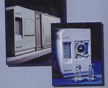
Massenspektrometer-Detektor MD 800 mit:
- Interface zur direkten Kopplung der Kapillarsäule mit der lonenquelle
- unabhängiger lnterfaceheizung bis 400°C
- schweißnahtlosem Außengehäuse (extrudiertes Aluminium)
- Hochleistungs-Quadrupolfilter
- Vorfiltern für optimale lonentransmission
- Massenbereich 2-800 Da
- Auflösungsvermögen justierbar bis 2,5
- optimierter EI-lonenquelle - unabhängiger lonenquellenheizung bis 350°C
- manueller und automatischer Optimierung der
- MS-Parameter (Autotuning, Autokalibrierung)
- computergesteuertem Referenzeinlaß
- Peakanzeige während des Tunings in Realtime
- DYNOLITE Detektionssystem, neuentwickelter Detektor mit zweifacher Konversionsdynode und geschlossenem Photomultiplier Steuerungs- und Datenerfassungselektronik
- variabler Ionisierungsenergie (0-70 eV)
- zweistufiger Vorpumpe - Turbomolekularpumpe (Pumpleistung 60 Ilsek)
Automatischer- Flüssig-Probengelber Modell A 105S
- Kapazität: 105 Standard-Probenfläschchen (NI I)
- Alle Bewegungsabäufe durch Schrittmotoren gesteuert
- Ansauggeschwindigkeit entsprechend der Viskosität der Probe individuell einstellbar
- Einspritzgeschwindigkeit einstellbar
- Anzahl der Spülschritte mit bis zu zwei Lösungsmitteln und/oder Probe sowie Volumen frei programmierbar
- 2ter Lösungsmittelvorrat als Option
- Kontrollierte "hot empty needle" Einspritztechnik möglich
- Einspritzvolumen max 10 PI in 0,l PI-Stufen
- Standardspritze 10 µl
- Probenteller mit Kühlwasseranschluß
- Eingabe und Kontrolle der Parameter über Keyboard und LCD- Display (2 X 16 Zeichen) - 10 Methodenspeicher für verschiedene Injektionsparameter-Sätze
- RS 232-Schnittstelle - Halterung für GC 8000MS
Hardware:
Rechner mit Bildschirm, Tastatur und Maus
Software
- Betriebssystem Windows NT 4
- GC-MS XCalibur
- NIST (NBS) Spektrenbibliothek (Bibliothek mit Ca. 63.000 Einzeleinträgen, Strukturformel- darstellung und Synonymdatenbasis


