Beckman Paragon 6558
| Objektnummer | B00013342 |
|---|---|
| ID-Nummer | 013342 |
| Objektbezeichnung | Beckman Paragon 6558 |
| Status | Archiviertes Produkt |
Produktgruppe: Elektrophorese
Status, Liefer- und Zahlungsbedingungen
Geräteüberprüfung
Die gebrauchten Laborgräte werden vor der Auslieferung von der Labexchange Service GmbH überprüft. Sie erhalten voll funktionsfähige Geräte.
Versandzeit
Die angegebenen Versandzeiten sind die jeweils kürzesten für einen Artikel. Die tatsächlich Versandzeiten können im Einzelfall davon abweichen. Die endgültigen Versandzeiten werden in der Auftragsbestätigung angegeben.
Bei Bestellung/Anfrage von mehreren Artikeln bieten wir grundsätzlich Sammellieferung an. Die Versandzeit berechnet sich nach der Position mit der längsten Versandzeit. Auf ausdrücklichen Wunsch ist eine Teillieferung möglich.
Versandarten
Paketdienste, Speditionen, Selbstabholung, Lieferung durch Labexchange-Fuhrpark
Lieferinformationen
Unsere Lieferbedingungen sind grundsätzlich zzgl. Versandkosten. Angegebene Versandkosten sind zu erwarten. Falls anfallende Versandkosten nicht angegeben sind, fragen Sie diese bitte gesondert an.
Die angegebenen Fracht- und Verpackungskosten beziehen sich auf den günstigsten Transportweg und sind vorbehaltlich unvorhergesehener Kostensteigerungen. Durch unvorhersehbare Ereignisse können sich die Frachtraten und die Lieferzeiten jederzeit ändern und müssten der aktuellen Situation angepasst werden. Incoterm-Kodierung gemäß Incoterms 2010: Bei Selbstabholung EXW, bei Sendungen per Schiff CFR, per Luftfracht CPT, übrige Sendungen DAP. Hinweis für Auslandssendungen: Ein Präferenznachweis/EUR1 wird von uns nicht ausgestellt. Bei Selbstabholung/EXW aus Drittländern und der EU werden 16% MWSt als Kaution einbehalten bis wir die Gelangensbestätigung/den Verbringungsnachweis des Käufers erhalten haben.
Zahlungsbedingungen
Wir akzeptieren keine Zahlung per Letter of Credit, PayPal etc. Der Rechnungsbetrag ist in jedem Fall ohne Abzug fällig. Die Ware bleibt bis zur vollständigen Bezahlung unser Eigentum. Skonto wird nicht gewährt.
|
Land |
Mögliche Zahlungsarten |
Bemerkung |
|
DE, AT, CH |
Rechnung, Vorkasse, Kreditkarte |
Eine Zahlung per Rechnung ist nur für Firmenkunden möglich. |
|
NL, BE, LU |
Rechnung, Vorkasse, Kreditkarte |
Eine Zahlung per Rechnung ist nur für Firmenkunden möglich. |
|
Alle weiteren Länder |
Vorkasse, Kreditkarte |
|
Es gelten unsere Allgemeinen Verkaufs-, Lieferungs- und Zahlungsbedingungen. Diese finden Sie hier. Zwischenverkauf, sowie Irrtum und Preisänderungen sind vorbehalten.
Statusdefinition
Alle Artikel sind gebrauchte Artikel, es sei denn ein Artikel wird explizit als Neugerät aufgeführt.
|
Status |
Zustand |
Bemerkung |
|
Sofort verfügbar |
gebraucht |
Der Artikel wurde bereits überprüft und befindet sich in einem einwandfreien Zustand. Er kann direkt an Sie versendet werden. |
| Lagergerät |
gebraucht |
Der Artikel befindet sich in unserem Lager. Unsere Techniker werden den Artikel vor der Auslieferung überprüfen. Sie erhalten voll funktionsfähige Artikel. |
|
Anbieter |
gebraucht |
Der Artikel befindet sich noch beim Anbieter. Nach Ihrer Bestellung wird er von uns angekauft, überprüft und an Sie versendet. Ein Funktionszertifikat und ein Servicebericht sind bei der Lieferung enthalten. |
|
Neugerät |
neu |
Es handelt sich um einen fabrikneuen Artikel. Es gelten die Garantiebestimmungen des Herstellers sowie die gesetzliche Gewährleistungsfrist. |
|
Labprocure |
gebraucht |
Verantwortlich für den Inhalt dieses Geräteangebotes ist die Labprocure GmbH als Geräteinserent. Labprocure übernimmt die Haftung für die hier inserierten Angebote und für die beinhalteten Fotos und Angebotstexte. Labprocure GmbH, Bruckstrasse 58, 72393 Burladingen. |
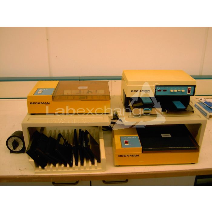
The following illustrations and descriptions are referring to the instrument model and are drawn from brochures. They are not representing the delivery volume. The exact delivery content you will find only in the offering text.
For In Vitro Diagnostic Use
INTENDED USE
Beckman's Paragon Cooled Electrophoresis Bridge consists of a cell cover and a cell bridge and is intended for use with the Paragon Cell and the Paragon Power Supply as an integrated assembly for performing electrophoretic separations on Paragon Gels. Each Bridge will accommodate one Gel.
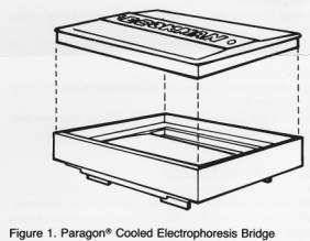
BRIDGE ASSEMBLY DESCRIPTION
The Paragon Cooled Electrophoresis Bridge, Figure 1, consists of two major components: the Bridge and the Lid. The Bridge consists of a curved surface and a reservoir for ice. The Bridge is used to support a Paragon Gel during electrophoresis. lt fits inside the vessel and enables each end of the Gel to extend into an electrolyte reservoir without touching the Center baffle. The Lid fits over the Bridge to cover the reservoir, thus eliminating the possibility of electrical shock and minimizing evaporation. A magnet in the Lid activates the safety interlock on the Power Supply.
INSTALLATION
The Bridge should be visually inspected upon arrival for evidence of damage caused in shipment. lf damage is evident, notify the carrier immediately. The Bridge is shipped ready for use. lt is designed to fit in the vessel and the entire unitor Cellconsisting of vessel, Bridge, and Lid is designed to connect to the Paragon Power Supply.
PRINCIPLE OF OPERATION
A Paragon Cooled Electrophoresis Bridge contains a reservoir which, when filled with water and frozen, acts to remove heat from the Gel during the electrophoresis. A Gel with sample applied is placed on the Bridge and the Bridge is placed in the vessel with the ends of the Gel extending into the electrolyte reservoirs. When
current is applied to the Cell, the Gel acts as a "media bridge" to complete the electrical circuit between both reservoirs. As the current passes through the Gel, the charged proteins migrate and an electrophoretic separation pattern is produced.
Voltage is supplied to each Cell from the Paragon Power Supply only when the Cell Lid is in place. The Lid activates the safety interlock on the Power Supply by means of a magnet mounted in the top of the Lid. Current flow through the Cell is indicated by an illuminated light-emitting diode (LED), at the stations (1 or 2), located on the front panel of the Power Supply, to which the Cell is connected.
OPERATING PROCEDURE
Take the following steps to place each Cell into Operation.
1. Be sure Bridge is clean and dry.
2. Fill Reservoir with 150 mL water.
3. Gently place Lid on Bridge, Figure 2. Be sure to properly align the Lid so that it closes completely.
4. Place Bridge with Lid in place on a level surface in a standard freezer (15°C to 20°C) for at least Tour (4) hours to ensure that water is completely frozen.
5. Prepare each Gel for Operation according to the instructions
which accompany the Paragon Reagent Test Kit in use.
6. Remove Bridge from freezer and allow to stand at room tem‑
perature for live (5) minutes prior to use.
7. Center the Gel over the Cooled Electrophoresis Bridge and gently bend the Gel so that it becomes concave. Be sure to align positive (+) and negative () sides of the Gel with corresponding positions marked on the Cooled Bridge. Insert the Gel edges under Bridge "feet." The slotted area on either side of the Bridge allows for easy insertion and removal of the Gel, Figure 3.
NOTE: Be sure Gel backing, not agarose, is in direct contact with curved cooling surface.

8. Invert Cooled Electrophoresis Bridge and place unit in the vessel containing buffer. Be sure to properly align Bridge so that the air vent is not obstructed.

9. Connect Cell to Power Supply by inserting it directly into the output jacks for position 1 or 2, Figure 4, if using only one Cell. Use both positions for two Cells.
NOTE: The Power Supply will not operate without one or two covered Cells in place.

10. Select the desired voltage by depressing the appropriate pushbutton on the Power Supply.
11. Place the ON/OFF Switch on the Power Supply to the ON position. The ON/OFF Switch will illuminate to indicate direct current voltage supply to the Cell. The proper Cell Indicator Light will illuminate to indicate current flow through the Cell.
12. At the completion of the electrophoretic run, place the ON/OFF Switch to the OFF position; set the Voltage Selector (VOLTS) to the lowest setting, i.e., 50 volts; and remove each Gell from the Power Supply.
13. With Lid attached, remove Bridge from Vessel; turn unit upside down; and remove Gel. Process Gel according to the instructions which accompany the Paragon Reagent Test Kit in use.
14. Remove Lid from Bridge and rinse the assembly with deionized water.
Paragon WET PROCESSOR
INTENDED USE
Beckman's Paragon Wet Processor is intended for use with Paragon Electrophoresis Reagent Test Kits.
WET PROCESSOR DESCRIPTION
The Paragon Wet Processor is designed for use atop a laboratory bench or table, Figure 1. The Wet Processor may also be used in conjunction with an optional Paragon Organizer, Figure 2. The Organizer is a bench-top platform that enables the user to keep the Paragon Power Supply, Incubator, Dryer, and Wet Processor in an orderly functional arrangement. The Organizer is equipped with a power strip that enables the user to connect all the electrical components; i.e., Power Supply, Incubator, and Dryer, into convenient outlets.
The Wet Processor consists of five reagent cups with covers, one Gel Frame Holder, two Gel Frames, and a molded tray to hold the reagent cups, Figure 1. The Wet Processor provides a neat and functional assembly to organize the reagents necessary for electrophoresis processing.
The unit is shipped ready for use.

INSTALLATION
The unit should be visually inspected upon arrival for evidence of damage caused in shipment. If damage is evident, notify the carrier immediately.
There are no special installation instructions or requirements.

HOW TO USE THE WET PROCESSOR
Take the following steps to use the Wet Processor:
1. Fill the reagent cups as directed in the instructions which
accompany the appropriate Paragon Reagent Test Kit.
2. After electrophoresis is completed, place the Gel into the
Gel Frame as shown in Figure 3.

3. Place one or two Gel Frames into the Gel Frame Holder, Figure 4.

4. The Gel Frame Holder, containing the Gel and Gel Frame, is then placed into the staining reagents according to the directions for the particular electrophoretic determination being performed.
Paragon® DRYER
INTENDED USE
Beckman's Paragon Dryer is intended for use in the normal post-electrophoretic process to dry electrophoretic support media.
DRYER DESCRIPTION
The Paragon Dryer is designed for use atop a laboratory bench or table, Figure 1. The Dryer may also be used in conjunction with an optional Paragon Organizer, Figure 2. The Organizer is a bench-top platform that enables the user to keep the Paragon Power Supply, Incubator, Dryer, and Wet Processor in an orderly functional arrangement. The Organizer is equipped with a power strip that enables the user to connect all the electrical components; i.e., Power Supply, Incubator, and Dryer, into convenient outlets.
The Dryer provides a uniformly distributed air flow through the compartment for drying electrophoresis support media. An illuminating power switch indicates when power is being supplied to the Dryer.
The unit is shipped ready for use.

INSTALLATION
The Dryer should be visually inspected upon arrival for evidence of damage caused in shipment. lf damage is evident, notify the carrier immediately.
The Dryer is intended for use in a laboratory environment where ambient temperatures are in the range of 18°C to 28°C and relative humidity in the range of 15% to 85%. The temperature of the Dryer may vary directly with changes

in ambient temperature. The Dryer control point is set to operate between 60°C and 70°C in ambient temperature. The time required to dry a Gel may vary slightly with the ambient temperature and relative humidity.
Extreme variation from either the ambient temperature or relative humidity may adversely affect operation of the Dryer.
An optional thermometer (Beckman Part 655994) may be used to check the temperature of the Dryer. The thermometer should be placed in the Center of the drying compartment for a minimum of 15 minutes.
The power cord for the Dryer is a three-wire grounded type to oe connected to a properly grounded outlet. A Dryer bearing the Beckman Part 655805 operates at 120 ± 15 volts, 50/60 Hz; Beckman Part 450036 operates at 240 ± 24 volts, 50/60 Hz. The nameplate an the rear panel provides the part number.
CAUTION
THE POWER CORD MUST BE CONNECTED TO AN OUTL.ET THAT WILL ACCEPT THE THREE-PRONGED PLUG AND PROVIDE THE REQUIRED ELECTRICAL GROUND. DO NOT OPERATE THE UNIT FROM A CONNECTION TO ANY TWO-PRONGED ADAPTER. DO NOTUNDER ANY CIRCUMSTANCESOPERATE THE UNIT FROM AN OUTLET THAT DOES NOT PROVIDE AN ELECTRICAL GROUND.
PRINCIPLE OF OPERATION
The Paragon Dryer features a heating element which allows air from a motor-driven fan to flow through it and be heated before flowing into the drying chamber and out through the
exhaust port to room air. The heater is designed to maintain the operating set point. The design of the Dryer prevents excessive drying of electrophoretic media because thermal run-away is not possible. lf the air flow through the heating element is interrupted, the heater turns off. lf the blower motor overheats, a nonresettable thermal fuse will trip.
SPECIFICATIONS
Input Voltage
Beckman Part 655805, 120 ± 15 volts, 50/60 Hz;
Beckman Part 450036 240 ± 24 volts, 50/60 Hz.
Case Dimensions
13" (33 cm) wide, 3-5/8" (9.2 cm) high, 8" (20.3 cm) deep.
Weight
3 pounds 7 ounces (1.6 kg).
Ambient Temperature
18°C to 28°C.
Relative Humidity
15% to 85%.
OPERATING CONTROL AND INDICATOR
Refer to Figure 1 for the location of the power switch and integral indicator lamp.
OPERATION PROCEDURE
Take the following steps to use the Dryer for drying electrophoretic support media:
1. Set the power switch to ON. Observe that the power switch indicator light illuminates.
2. Allow thirty minutes for the Dryer to reach operating temperature.
3. Place the Gel into the Gel Frame, Figure 3, open the cover, and place the Gel Frame into the Dryer. Close the cover.

The time required to dry a Gel may vary with the ambient temperature, relative humidity, and input voltage level. The Dryer will hold up to two Gels.
Paragon POWER SUPPLY
INTENDED USE
Beckman's Paragon Power Supply is intended for use with one or two Paragon Cells as an integrated assembly for electrophoretic separations which require a d.c. potential of 50, 100, 150, or 200 volts. The Power Supply unit may be used to power either a single Paragon Cell or two Paragon Cells simultaneously.
POWER SUPPLY DESCRIPTION
The Paragon Power Supply, Figure 1, is designed for use atop a laboratory bench or table. The Power Supply may also be used in conjunction with an optional Paragon Organizer, Figure 2. The Organizer is a bench-top platform that enables the user to keep the Paragon Power Supply, Incubator, Dryer, and Wet Processor in an orderly, functional arrangement. The Organizer is equipped with a power strip that enables the user to connect all the electrical components of the Paragon System; i.e., Power Supply, Incubator, and Dryer, into convenient outlets.

1. Power SwitchAn illuminated neon lamp indicates the d.c. potential at the output jacks.
2. Voltage Selection SwitchesPush one of four voltage pushbutton switches to select the desired voltage to be applied to the Cell(s).
3. Current Indication LED'sCELL 1 LED and GELL 2 LED are used to indicate current flow to the designated covered Cell(s) which contain the support medium.
4. Output JacksEach pair of jacks accepts one Paragon Cell. The Power Supply can power two Cells simultaneously. The red jack is used to indicate the anode electrode of the Cell and the direction of protein migration.
Figure 1. ParagonTM Power Supply
The Power Supply, Figure 1, provides constant d.c. power with a selectable output voltage of 50, 100, 150, or 200 volts. The Power Supply will provide the selected voltages to a single Paragon Cell or two Paragon Cells simultaneously. The Power Supply will not operate without a covered Cell in place. The d.c. potential will not be supplied to an empty station jf only one Cell is used.

An optional mechanical Timer, Figure 2, may be set to establish electrophoretic run periods of up to sixty minutes. At the end of the time period selected, power is removed from the Power Supply, and thereby, power is removed from the Cell. The Timer is employed by simply connecting it to a standard three-wire grounded power outlet. The Power Supply is then connected to the Timer.
The Power Supply is shipped ready for use.
INSTALLATION
The Power Supply should be visually inspected upon arrival for evidence of damage caused in shipment. If damage is evident, notify the carrier immediately.
The power cord for the Power Supply is a three-wire grounded type to be connected to a properly grounded electrical outlet. A Power Supply bearing Beckman Part 655803 operates from 120 ± 15 volts, 50/60 Hz; Beckman Part 655804 operates from 240 ±30 volts, 50/60 Hz. The nameplate an the rear panel provides the part number. Confirm that the voltage requirements match the laboratory power.
CAUTION
THE POWER CORD MUST BE CONNECTED TO AN OUTLET THAT WILL ACCEPT THE THREE-PRONGED POWER PLUG AND PROVIDE THE REQUIRED ELECTRICAL GROUND. DO NOT OPERATE THE UNIT FROM A CONNECTION WITH ANY TWO-PRONGED ADAPTER. DO NOTUNDER ANY CIRCUMSTANCESOPERATE THE UNIT FROM AN OUTLET THAT DOES NOT PROVIDE AN ELECTRICAL GROUND.
PRINCIPLE OF OPERATION
The Paragon Power Supply transforms a.c. line voltage through a power transformer to the voltage rectifier and regulator circuitry. This solid-state circuitry provides well-regulated d.c. voltages, as selected. The specific output voltage is selected by pressing one of the four voltage setting switches; 50 V, 100 V, 150 V, or 200 V. The selected d.c. voltage will output only to Paragon Cells which have Lids in place. Each Lid activates the safety interlock on the Power Supply by means of a magnet mounted in the top of the Lid. Current flow through the Cell is indicated by an illuminated light emitting diode (LED), at the station indicated on the front panel (1 or 2).
SPECIFICATIONS
Available Voltage Output
50 -1-1.5 volts, 100 ± 2 volts, 150 ± 3 volts, 200 ± 4 volts.
Input Voltage
Beckman Part 655803, 120 ± 15 volts, 50/60 Hz.
Beckman Part 655804, 240 ± 30 volts, 50/60 Hz.
Case Dimensions
11-1/2" (24.2 cm) wide, 5-1/2" (14 cm) high, 7-1/8" (18.1 cm) deep.
Weight
5.25 pounds (1.4 kg).
OPERATING CONTROLS AND INDICATORS
Refer to Figure 1 for a functional description of the operating controls and indicators located on the front panel.
OPERATING PROCEDURE
Take the following steps to place the Power Supply and each Cell into operation:
1. Prepare each Gel and each Cell for electrophoresing according to the instructions which accompany the Paragon Reagent Test Kit.
2. With the Power Supply properly connected to an electrical outlet, ensure that the ON/OFF Switch is in the OFF position.
3. Cover each Cell and connect it to the Power Supply by inserting it directly into the output jacks for position 1 or 2 of the Power Supply, if using only one Cell. Use both positions for two Cells. A detailed explanation for the placement of the Cell into the Power Supply can be found in the Beckman Paragon Electrophoresis Manual (Beckman Instructions 015-556569).
NOTE
The Power Supply will not operate without one or two covered Cells in place. Refer to Figure 3 for an Illustration of Cell placement in the Power Supply.
4. Select the desired voltage by depressing the proper pushbutton.
5. Place the ON/OFF Switch to the ON position. The ON/ OFF Switch will illuminate to indicate the d.c. voltage supply to the Cell. The proper Cell indicator light will illuminate to indicate current flow through each Cell.
NOTE
lf the optional Timer is employed, set the Timer to the appropriate run time (if less than ten minutes, turn past ten, then set time). At the end of the selected run time, the Timer will automatically turn off power to the Power Supply.
6. At the completion of the electrophoretic run, place the ON/OFF Switch to the OFF position, set the Voltage Selector (VOLTS) to the lowest setting; i.e., 50 volts, and remove each Cell.
Paragon® INCUBATOR
INTENDED USE
Beckman's Paragon Incubator is intended for use in postelectrophoretic procedures, such as those performed for isoenzymes.
INCUBATOR DESCRIPTION
The Paragon Incubator, Figure 1, is designed for use atop a laboratory bench or table. The Incubator may also be used in conjunction with an optional Paragon Organizer, Figure 2. The Organizer is a benchtop platform that enables the user to keep the Paragon Power Supply, Incubator, Dryer, and Wet Processor in an orderly functional arrangement. The Organizer is equipped with a power strip that enables the user to connect all the electrical components; i.e., Power Supply, Incubator, and Dryer, into convenient outlets. Incubator boxes are supplied to provide a moist, dark environment for the Gel during incubation.
The Incubator provides a controlled temperature of 45°C. An illuminating power switch indicates when power is being supplied to the Incubator.
The Incubator is shipped ready for use.

INSTALLATION
The Incubator should be visually inspected upon arrival for evidence of damage caused in shipment. If damage is evident, notify the carrier immediately.
The Incubator is intended for use in a laboratory environment where ambient temperatures are in the range of 18°C to 28°C and relative humidity in the range of 15% to 85%.

Extreme variances from either the ambient temperature or relative humidity may adversely affect operation of the unit.
An optional thermometer (Beckman Part 655994) may be used to check the temperature of the dryer.
The power cord for the unit is a three-wire grounded type to be connected to a properly-grounded electrical outlet. A unit bearing the Beckman Part 655807 operates at 120 ± 15 volts, 50/60 Hz; Beckman Part 655808 operates at 240 ±30 volts, 50/60 Hz. (At voltages above 240 volts, there is an internal heating effect on the contact struts. This heating effect causes a downward control point shift of approximately 0.3°C per volt. Because the shift is downward, there is no harm to the Gel from overheating.) The nameplate on the rear panel provides the part number.
CAUTION
THE POWER CORD MUST BE CONNECTED TO AN OUTLET THAT WILL ACCEPT THE THREE-PRONGED POWER PLUG AND PROVIDE THE REQUIRED ELECTRICAL GROUND. DO NOT OPERATE THE UNIT FROM A CONNECTION TO ANY TWO-PRONGED ADAPTER. DO NOTUNDER ANY CIRCUMSTANCESOPERATE THE UNIT FROM AN OUTLET THAT DOES NOT PROVIDE AN ELECTRICAL GROUND.
PRINCIPLE OF OPERATION
The temperature of the Incubator is maintained at 45°C ±2°C by a thermostatically controlled heating element. The Gel should be placed in one of the included Incubator boxes, before being placed in the Incubator chamber. Each box accomodates one Gel and provides a moist, dark environment for the Gel during incubation.
SPECIFICATIONS
Input Voltage
Beckman Part 655807, 120 ±15 volts, 50/60 Hz;
Beckman Part 655808, 240 ±30 volts, 50/60 Hz.
Case Dimensions
13" (33 cm) wide, 3-3/8" (9.2 cm) high, 8" (20.3 cm) deep.
Weight
3 pounds 7 ounces (1.6 kg).
Ambient Temperature
18°C to 28°C.
Relative Humidity
15% to 85%.
OPERATING CONTROL AND INDICATOR
Refer to Figure 1 for the location of the power switch and integral indicator lamp.
OPERATING PROCEDURE
Take the following steps to put the unit in operation:
1. Set the power switch to ON. Observe that the power indicator light illuminates.
2. Allow thirty minutes for the Incubator to reach operating temperature.
3. Place each Gel into an Incubator box, open the cover, insert the Incubator box, and close the cover. The Incubator will hold up to two Incubator boxes.
TEMPERATURE ADJUSTMENT PROCEDURE
1. Check serial number of incubator unit. For serial numbers 1094 and below, replace the unit through the HOTLINE, by calling toll-free 1-800-854-3633. For serial numbers 1095 and above, proceed with Steps 2 through 7.
2. Turn unit on and allow 30 minutes warmup.
3. Position thermometer bulb at center of plate.
4. Turn unit around (back facing you) and locate the small copper adjustment screw inside the rear vent (on righthand side).
5. With a small screwdriver, adjust temperature by rotating the screw one (1) turn clockwise for 3°C of needed increase, or one (1) turn counterclockwise for 3°C decrease in temperature.
6. Ailow 30 minutes for stabilization and recheck temperature.
7. Repeat Steps 3 through 5 as necessary.


