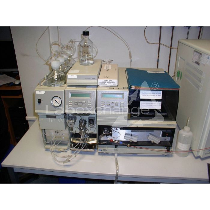
Thermo LCQ DECA
| Objektnummer | B00018595 |
|---|---|
| Seriennummer | 018595 |
| Object Naam | Thermo LCQ DECA |
| Status | Gearchiveerd product |
Product groep: LC / MS
Status, leverings- en betalingsvoorwaarden
Apparatuurcontrole
De gebruikte apparatuur wordt voorafgaand aan levering gecontroleerd door Labexchange Service GmbH. U ontvangt volledig functionerende apparatuur.
Verzending
De vermelde verzendtijden zijn telkens de kortste voor een artikel. In bepaalde gevallen kunnen de daadwerkelijke verzendtijden daarvan afwijken. De uiteindelijke verzendtijden worden aangegeven in de opdrachtbevestiging.
In de regel bieden we combinatieleveringen aan. Levertijden zijn afhankelijk van het artikel met de langste levertijd. Deelleveringen zijn mogelijk tegen een toeslag.
Verzendmethoden
Koeriersdiensten, transportbedrijven, zelf afhalen, levering door Labexchange wagenpark
Informatie levering
De prijzen zijn exclusief verzendkosten. De genoemde verzendkosten zijn de te verwachten kosten. Afwijkingen zijn mogelijk. In het geval geen kosten voor verzending zijn gespecificeerd, vraag die dan afzonderlijk aan.
De opgegeven vracht- en verpakkingskosten hebben betrekking op de goedkoopste transportroute en zijn onder voorbehoud van onvoorziene kostenstijgingen. Door onvoorziene gebeurtenissen kunnen vrachttarieven en levertijden op elk moment veranderen en moeten ze worden aangepast aan de huidige situatie. Incoterm coderingen volgens Incoterms 2010: Bij afhalen EXW, CFR voor zendingen over zee, CPT per luchtfracht, andere zendingen DAP. Opmerking: We geven geen preferentieel certificaat/EUR1 af. Bij zelf afhalen/af fabriek (EXW) uit derde landen en de EU wordt 16% btw als borg ingehouden, tot we de ontvangstbevestiging/het leveringscertificaat van de koper hebben ontvangen.
Betalingsvoorwaarden
Wij accepteren geen betalingen Letter of Credit, PayPal etc. Het factuurbedrag is volledig verschuldigd. Er zijn geen betalingskortingen. De goederen blijven tot volledige betaling ons eigendom.
|
Land |
Mogelijke betaalmethoden |
Opmerking |
|
Duitsland, Oostenrijk, Zwitserland |
Betaling via factuur, vooruitbetaling, per creditkaart |
Betaling via factuur is mogelijk voor ondernemingsklanten. |
|
Nederland, België en Luxemburg |
Betaling via factuur, vooruitbetaling, per creditkaart |
Betaling via factuur is mogelijk voor ondernemingsklanten. |
|
Andere landen |
vooruitbetaling, per creditkaart |
|
Onze Algemene Voorwaarden voor Verkoop, Levering en Betaling zijn hierop van toepassing. Deze voorwaarden zijn hier te downloaden.
Tussenverkoop is ons voorbehouden.
Beschrijving status:
Alle artikelen zijn gebruikte artikelen, tenzij bij een artikel uitdrukkelijk wordt vermeld dat het om een nieuw apparaat gaat.
The following illustrations and descriptions are referring to the instrument model and are drawn from brochures. They are not representing the delivery volume. The exact delivery content you will find only in the offering text.
API Source
The atmospheric pressure ionization (API) source forms gas phase sample ions from sample molecules that are contained in solution. The API source also serves as the sample interface between the LC and the MS detector. You can operate the API source in either the electrospray ionization (ESI) or atmospheric pressure chemical ionization (APCI) mode.
The API source consists of two assemblies:
API probe assembly (ESI or APCI)
API stack
API Probe Assembly
The API probe assembly is the portion of the API source that is external to the vacuum manifold. You can change the ionization mode of the MS detector and switch the probe assemblies without breaking the vacuum. Two API probe assemblies are available with the LCQDECA:
ESI probe assembly
APCI probe assembly
ESI Probe Assembly
The ESI probe assembly consists of the ESI flange and the ESI probe. See Figure 1-1. The ESI flange holds the ESI probe in position next to the entrance of the heated capillary, which is part of the API stack. The ESI flange also seals the atmospheric pressure region of the API source. In addition, when it is in the operating Position against the spray shield, the ESI flange compresses the high-voltage safety-interlock switch. The ESI flange mounts an rails that allow movement of the flange toward and away from the vacuum manifold for easy servicing. Two flange retainer bolts hold the flange in place against the spray shield of the API stack. A grounded fltting holder secures a stainless steel grounded fitting that connects the sample transfer line to the PEEK safety sleeve and fused-silica sample tube.
The ESI probe produces charged aerosol droplets that contain sample ions. The ESI probe accommodates liquid flows of 1 µL/min to 1 mL/min without splitting.
The ESI probe includes the ESI fused-silica sample tube and PEEK safety sleeve, needle, nozzle, and manifold. Sample and solvent enter the ESI probe through the fused-silica sample tube. The sample tube is a short section of 0.1 mm ID fused-silica capillary that extends from a Fingertight fitting and ferrule secured to the grounded fitting holder, through the sample inlet and into the ESI needle, to within 1 mm from the end of the ESI needle. The ESI needle, to which a large negative or positive voltage is applied (typically ±4.5 to ±5 kV), sprays the sample solution into a fine mist of charged droplets. The ESI nozzle directs the flow of sheath gas and auxiliary gas at the droplets. The ESI manifold houses the ESI nozzle and needle and includes the sheath gas, auxiliary gas, and sheath liquid plumbing. The sheath gas plumbing and auxiliary gas plumbing deliver dry nitrogen gas to the nozzle. The sheath liquid plumbing delivers sheath liquid to the nozzle.
The ESI probe has inlets for the introduction of sample solution, sheath gas, auxiliary gas, and sheath liquid into the API source. The sheath gas is an inner coaxial nitrogen gas that sprays (nebulizes) the sample solution into a fine mist as it exits the sample tube. Typical sheath gas flow rates for ESI are 20 to 40 psi for sample flow rates of 5 to 10 µL/min and 80 units for sample flow rates of 200 to 1000 µ/min. When you tune the LCQDECA, you may need to adjust the sheath gas flow rate until the ion signal is stable.
The auxiliary gas is an outer coaxial nitrogen gas that assists the sheath gas in the nebulization and evaporation of sample solutions. The auxiliary gas also helps lower the humidity in the ion source. Typical auxiliary gas flow rates for ESI are 10 to 20 units. Auxiliary gas is usually not needed for sample flow rates below 100 mL/min. Refer to Table 1-1 for specific guidelines for LC/ESI/MS operation.
The sheath liquid is a solvent used to stabilize and enhance the ESI process for some solution chemistries (for example, high aqueous content) that do not readily form an electrospray and to provide make-up solvent in CE and CEC applications. Sheath liquid is injected by the syringe pump and exits the nozzle coaxially to the sample tube.


Table 1-1. Guidelines for LC/ESI/MS Opteration
|
LC Flow Rates |
Suggested Column Size |
Probe Position (1 to 4) |
Heated Capillary Temperature |
Sheath Gas |
Auxiliary Gas |
|
Infusion or LC at flow rates of <10 µL/min |
Capillary |
2 |
Typical setting: 150 to 275 °C |
Required Typical setting: 20 to 40 units |
Not required Typical setting: 0 units |
|
LC at flow rates from 50 to 100 µL/min |
1 mm ID |
2 |
Typical setting: 350 °C |
Required Typical setting: 80+ units |
Not required, but might heip depending on conditions |
|
LC at flow rates from 200 to 500 µL/min |
2 to 3 mm ID |
3 |
Typical setting: 350 °C |
Required Typical setting: 80+ units |
Not required, but usually helps to reduce solvent background ions Typical setting: 20 units |
|
LC at flow rates from 0.5 to 1 mL/min |
4.6 mm ID |
3-4 |
Typical setting: 350 °C |
Required Typical setting: 80 to 100 units |
Required Typical setting: 20 units |
|
Note. In negative ion mode, waveform 2 might be required (depending on solvents and modifiers used). In positive ion mode with flow rates of >400 µL/min, waveform 2 might be required. |
|||||
APCI Probe Assembly
The APCI probe and flange assembly is a single molding including the corona discharge needle assembly. See Figure 1-2. The APCI flange holds the APCI probe and the corona discharge needle assembly in position next to the entrance of the heated capillary. As with the ESI flange, the APCI flange seals the atmospheric pressure region (also called the spray chamber) of the API source. The APCI flange mounts on rails that allow movement of the flange toward and away from the vacuum manifold for easy servicing. Two flange retainer bolts hold the flange in place against the spray shield of the API stack. When the APCI flange is in the operating position against the spray shield, it compresses the high-voltage safety-interlock switch.
The APCI probe ionizes the Sample by atmospheric pressure chemical ionization. The APCI probe accommodates liquid flows of 100 pL/min to 2 mL/min without splitting.
The APCI probe includes the APCI sample tube, nozzle, sheath gas and auxiliary gas plumbing, and vaporizer. Sample and solvent enter the APCI nozzle through the sample tube. The sample tube is a short section of 0.15 mm ID fused silica tubing that extends from the sample inlet to 1 mm past the end of the nozzle. The manifold houses the APCI nozzle and includes the sheath gas and auxiliary gas plumbing. The APCI nozzle sprays the sample solution into a fine mist. The sheath gas and auxiliary gas plumbing deliver dry nitrogen gas to the nozzle. Typical sheath gas flow rates for APCI are 60 units for sample flow rates of 100 µL/min, 80 units for sample flow rates of 1 mL/min, and 85 units for sample flow rates of 2 mL/min. Typical auxiliary gas flow rates for APCI are 10 to 20 units. The droplets in the mist then enter the vaporizer. The vaporizer flash vaporizes the droplets at temperatures up to 600 °C. Typical vaporizer temperatures are 450 to 550 °C for most flow rates. Refer to Table 1-2 for specific guidelines for LC/APCl/MS Operation.
Table 1-2. Guidelines for LC/APCI/MS Operation
|
LC Flow Rate |
Heated Capillary Temperature |
Vaporizer Temperature |
Sheath Gas |
Auxiliary Gas |
|
LC at flow rates from 0.2 to 2 mL/min |
Typical setting: 150 to 225 °C |
Typical setting: 400 to 550 °C |
Required Typical setting: 50 to 100 units |
Not required, but usually helps to reduce solvent background ions Typical setting: 0 to 20 units |
The sample vapor is swept toward the corona discharge needle by the flow of the sheath and auxiliary gasses. The corona discharge needle assembly is mounted an the APCI flange. The assembly positions the tip of the corona discharge needle near the vaporizer. A high potential (typically ±3 to ±5 kV) is applied to the corona discharge needle to produce a corona discharge current of up to 10 µA. (A typical value of the corona discharge current is 5 µA.) The corona discharge from the needle produces a reagent ion plasma primarily from the solvent vapor. The sample vapor is ionized by ion-molecule reactions with the reagent ions in the plasma. APCI requires a constant source of electrons for the ionization process. Thus, the corona discharge current is set and regulated. The potential applied to the corona discharge needle varies, as needed, to provide the required current.

Onze Labexchange-team zullen u graag helpen:

Christian Schmid
Laboratorium en analytiek, Laboratoriuminrichting, Life science

Hubert Sauter
Spectroscopie, Chromatografie


