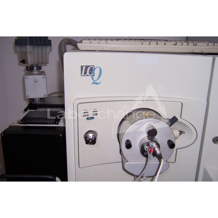
Thermo Finnigan LCQ
| Objektnummer | B00018388 |
|---|---|
| Seriennummer | 018388 |
| Object Naam | Thermo Finnigan LCQ |
| Status | Gearchiveerd product |
Product groep: LC / MS
Status, leverings- en betalingsvoorwaarden
Apparatuurcontrole
De gebruikte apparatuur wordt voorafgaand aan levering gecontroleerd door Labexchange Service GmbH. U ontvangt volledig functionerende apparatuur.
Verzending
De vermelde verzendtijden zijn telkens de kortste voor een artikel. In bepaalde gevallen kunnen de daadwerkelijke verzendtijden daarvan afwijken. De uiteindelijke verzendtijden worden aangegeven in de opdrachtbevestiging.
In de regel bieden we combinatieleveringen aan. Levertijden zijn afhankelijk van het artikel met de langste levertijd. Deelleveringen zijn mogelijk tegen een toeslag.
Verzendmethoden
Koeriersdiensten, transportbedrijven, zelf afhalen, levering door Labexchange wagenpark
Informatie levering
De prijzen zijn exclusief verzendkosten. De genoemde verzendkosten zijn de te verwachten kosten. Afwijkingen zijn mogelijk. In het geval geen kosten voor verzending zijn gespecificeerd, vraag die dan afzonderlijk aan.
De opgegeven vracht- en verpakkingskosten hebben betrekking op de goedkoopste transportroute en zijn onder voorbehoud van onvoorziene kostenstijgingen. Door onvoorziene gebeurtenissen kunnen vrachttarieven en levertijden op elk moment veranderen en moeten ze worden aangepast aan de huidige situatie. Incoterm coderingen volgens Incoterms 2010: Bij afhalen EXW, CFR voor zendingen over zee, CPT per luchtfracht, andere zendingen DAP. Opmerking: We geven geen preferentieel certificaat/EUR1 af. Bij zelf afhalen/af fabriek (EXW) uit derde landen en de EU wordt 16% btw als borg ingehouden, tot we de ontvangstbevestiging/het leveringscertificaat van de koper hebben ontvangen.
Betalingsvoorwaarden
Wij accepteren geen betalingen Letter of Credit, PayPal etc. Het factuurbedrag is volledig verschuldigd. Er zijn geen betalingskortingen. De goederen blijven tot volledige betaling ons eigendom.
|
Land |
Mogelijke betaalmethoden |
Opmerking |
|
Duitsland, Oostenrijk, Zwitserland |
Betaling via factuur, vooruitbetaling, per creditkaart |
Betaling via factuur is mogelijk voor ondernemingsklanten. |
|
Nederland, België en Luxemburg |
Betaling via factuur, vooruitbetaling, per creditkaart |
Betaling via factuur is mogelijk voor ondernemingsklanten. |
|
Andere landen |
vooruitbetaling, per creditkaart |
|
Onze Algemene Voorwaarden voor Verkoop, Levering en Betaling zijn hierop van toepassing. Deze voorwaarden zijn hier te downloaden.
Tussenverkoop is ons voorbehouden.
Beschrijving status:
Alle artikelen zijn gebruikte artikelen, tenzij bij een artikel uitdrukkelijk wordt vermeld dat het om een nieuw apparaat gaat.
The following illustrations and descriptions are referring to the instrument model and are drawn from brochures. They are not representating the delivery volume. The exact delivery content you will find only in the offering text.
Overview
Welcome to the LCQ data system!
LCQ is an advanced mass spectrometer (MS) detector that performs real-time mass analyses of LC eluents over a mass-tocharge ratio range of 50 to 2000.
You control LCQ using the Navigator window. The Navigator window provides menu commands, function buttons, and displays real-time sample status, chromatograph plot, and spectrum plot.
The Navigator window also provides access to LCQ windows that assest:
Setting up an experiment method for the solvent program, autosampler, chromatograph, MS Detector, and syringe pump (Experiment Method window)
Setting up the sequence and identity of the samples to be analyzed (Sample List window)
Component calibration, component quantification, and printing summary reports (Processing Method window)
Analyzing and annotating MS detector sample results (Explore window)
Reviewing and editing peak detection and integration criteria (Rework window)
Tuning and calibrating the MS detector and performing real-time experiments (Tune Plus window)
System Specifications
|
Parameter |
Specification |
|
Mass Range |
m/z 50 through 2000 |
|
Scan Power |
MS, MS/MS, and MS n , for n = 1 through 10 |
|
Scan Modes |
Full, SIM, SRM, CRM, and ZoomScan |
|
Scan Data Types |
Profile and centroid |
|
Ion Polarity |
Positive and negative |
|
Interchangeable Ion Sources |
ESI or APCI |
|
Monitor Screen resolution |
1024 x 768 pixels or higher resolution |
|
Operating System |
Microsoft Windows NT TM |
|
Communication Protocols |
Ethernet, TCP/IP, RS232, and IEEE 488 |
Syringe Pump
The LCQ includes an electronically-controlled, integrated, dual syringe pump. The syringe pump delivers sample solution and/or sheath liquid from the syringes into the API source. See Figure 2-2. When the syringe pump is operating, a motor drives a pusher block that depresses the plunger of the syringe at a controlled rate. Liquid flows out of the syringe needle and into the sample transfer line or sheath liquid line as the plunger is depressed. The syringe is held in place by a syringe holder. Refer to the topic Setting Up the Inlet: Syringe Pump in the LCQ Operator's Manual for instructions on setting up the syringe pump.
You can control the syringe pump from the LCQ data system. You specify the syringe type (manufacturer), syringe volume, syringe ID, and flow rate in the Syringe Pump dialog box, which can be reached from either the Tune Plus window or the Experiment Method window. Refer to the online Help and the Tune Plus and Experiment Method chapters of the LCQ Software Manual for instructions on operating the syringe pump from the data system.
You can start and stop the syringe pump from the data system or by pressing the start/stop button. The syringe pump LED is illuminated whenever the syringe pump is pumping.

Figure 2-2. Syringe pump
MS Detector
The MS detector provides sample ionization and mass analysis of injected samples or samples eluted from a liquid chromatograph. The LCQ MS detector uses a quadrupole ion trap mass analyzer with an ion source external to the mass analyzer. Several important features of the LCQ MS detector are as follows:
Universal, selective, and specific detector
High sensitivity
m /z 50 to 2000 mass range
ESI and APCI ionization modes
Positive and negative ion polarity modes
MSn with scan powers of n = 1 to 10
Full scan, SIM, SRM, CRM, and ZoomScan scan modes
The MS detector includes the following components:
Controls and indicators
API source
Ion optics
Mass analyzer
Ion detection system
Vacuum system and inlet gasses hardware
Cooling fans
Electronic assemblier

Figure 2-6. Power panel
The reset button (labeled Reset) is also located on the power panel. When you press the reset button, LCQ software is reloaded from the data system. Refer to the topic Resetting the MS Detector in the System Shutdown, Startup, and Reset chapter for information on resetting the MS detector.
ESI Probe Assembly
The ESI probe assembly consists of the ESI flange and the ESI probe. See Figure 2-7 and Figure 2-8. The ESI flange holds the ESI probe in position next to the entrance of the heated capillary, which is patt of the API stack (see below). The ESI flange also seals the atmospheric pressure region of the API source; and, when it is in the operating position against the spray shield, compresses the high-voltage safety-interlock switch. The ESI flange mounts an teils that allow movement of the flange toward and away from the vacuum manifold for easy servicing. Two flange retainer bolts hold the flange in place against the spray shield of the API stack. Agrounded fitting holder secures a fitting that connects the sample transfer line to the ESI sample tube. Aprobe retainer bolt secures the ESI probe to the ESI flange.

Figure 2-7. ESI probe assembly
The ESl probe produces charged aerosol droplets that contain sample ions. The ESI probe accommodates liquid flows of 1 µL min -1 to 1 mL min -1 without splitting.
The ESI probe includes the ESI sample tube, needle, nozzle, and manifold. Sample and solvent enter the ESI probe through the sample tube. The sample tube is a short section of 0.1 mm ID fused-silica tubing that extends from a fitting secured to the grounded fitting holder, through the sample inlet and into the ESI needle, to within 1 mm from the end of the ESI needle. The ESI needle, to which a large negative or positive voltage is applied (typically ±4.5 to ±5 kV), sprays the sample solution into a fine mist of charged droplets. The ESI nozzle directs the flow of sheath gas and auxiliary gas at the droplets. The ESI manifold
houses the ESI nozzle and needle and includes the sheath gas, auxiliary gas, and sheath liquid plumbing. The sheath gas plumbing and auxiliary gas plumbing deliver dry nitrogen gas to the nozzle. The sheath liquid plumbing delivers sheath liquid to the nozzle.
The ESI probe has inlets for the introduction of sample solution, sheath gas, auxiliary gas, and sheath liquid into the API source. The sheath gas is the inner coaxial nitrogen gas that sprays (nebulizes) the sample solution into a Eine mist as it exits the sample tube. Typical sheath gas flow rates for ESI are 60 units for sample flow rates of 3µL min -1 and 80 units for sample flow rates of 1 mL min -1 . (Typical sheath gas flow rates for APCI are 60 units for sample flow rates of 100 gL min -1 , 80 units for sample flow rates of 1 mL min -1 , and 85 units for sample flow rates of 2 mL min -1 .) When you tune the LCQ, you should adjust the sheath gas flow rate until the ion signal is stable.
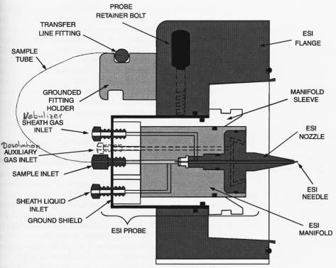
Figure 2-8. Cross sectional view of the ESI probe assembly
APCI Probe Assembly
The APCI probe assembly includes the APCI flange, the APCI probe, and the corona discharge needle assembly. See
Figure 2-9 and Figure 2-10. The APCI flange holds the APCI probe and the corona discharge needle assembly in position next to the entrance of the heated capillary (see below). As with the ESI flange, the APCI flange seals the atmospheric pressure region (also called the spray chamber) of the API source. The APCI flange mounts an rails that allow movement of the flange toward and away from the vacuum manifold for easy servicing. Two flange retainer bolts hold the flange in place against the spray shield of the API stack. When the APCI flange is in the operating position against the spray shield, it compresses the high-voltage safetyinterlock switch. Aprobe retainer bolt secures the APCI probe to the APCI flange.
The APCI probe ionizes the sample by atmospheric pressure chemical ionization. The APCI probe accommodates liquid flows of 100 µL min -1 to 2 mL min -1 without splitting. The APCI probe includes the APCI sample tube, nozzle, sheath gas and auxiliary gas plumbing, and vaporizer. Sample and solvent enter the APCI nozzle through the sample tube. The sample tube is a short section of 0.15 mm ID fused silica tubing that extends from the sample inlet to 1 mm past the end of the nozzle. The manifold houses the APCI nozzle and includes the sheath gas and auxiliary gas plumbing. The APCI nozzle sprays the sample solution into a Eine mist. The sheath gas and auxiliary gas plumbing deliver dry nitrogen gas to the nozzle. The droplets in the mist then enter the vaporizer. The vaporizer flash vaporizes the droplets at temperatures up to 800 °C.

Figure 2-9. APCI probe assembly
Typical vaporizer temperatures are 350 to 400 °C for flow rates of 100 µL min -1 , 450 to 500 °C for 1 mL min -1 (normal APCI flow rate), and 550 to 600 °C for 2 mL min -1 . The sample vapor is swept toward the corona discharge needle by the flow of the sheath and auxiliary gassec.
The corona discharge needle assembly is mounted an the APCI flange. The assembly positions the tip of the corona discharge needle near the vaporizer. A high potential (typically ±3 to ±5 kV) is applied to the corona discharge needle to produce a corona discharge current of up to 10 µA. (A typical value of the corona discharge current is 5µA.) The corona discharge from the needle produces a reagent ion Plasma primarily from the solvent vapor.
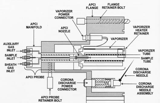
Figure 2-10. Cross sectional view of the APCI probe assembly
The sample vapor is ionized by ion-molecule reactions with the reagent ions in the Plasma.
APCI requires a constant source of electrons for the ionization process. Thus, the corona discharge current is set and regulated. The potential applied to the corona discharge needle varies, as needed, to provide the required current.
Onze Labexchange-team zullen u graag helpen:

Christian Schmid
Laboratorium en analytiek, Laboratoriuminrichting, Life science

Hubert Sauter
Spectroscopie, Chromatografie


