
Rheodyne Ventil 7725 i
| Objektnummer | B00013504 |
|---|---|
| Seriennummer | 013504 |
| Object Naam | Rheodyne Ventil 7725 i |
| Status | Stock unit |
Product groep: HPLC diversen
Status, leverings- en betalingsvoorwaarden
Apparatuurcontrole
De gebruikte apparatuur wordt voorafgaand aan levering gecontroleerd door Labexchange Service GmbH. U ontvangt volledig functionerende apparatuur.
Verzending
De vermelde verzendtijden zijn telkens de kortste voor een artikel. In bepaalde gevallen kunnen de daadwerkelijke verzendtijden daarvan afwijken. De uiteindelijke verzendtijden worden aangegeven in de opdrachtbevestiging.
In de regel bieden we combinatieleveringen aan. Levertijden zijn afhankelijk van het artikel met de langste levertijd. Deelleveringen zijn mogelijk tegen een toeslag.
Verzendmethoden
Koeriersdiensten, transportbedrijven, zelf afhalen, levering door Labexchange wagenpark
Informatie levering
De prijzen zijn exclusief verzendkosten. De genoemde verzendkosten zijn de te verwachten kosten. Afwijkingen zijn mogelijk. In het geval geen kosten voor verzending zijn gespecificeerd, vraag die dan afzonderlijk aan.
De opgegeven vracht- en verpakkingskosten hebben betrekking op de goedkoopste transportroute en zijn onder voorbehoud van onvoorziene kostenstijgingen. Door onvoorziene gebeurtenissen kunnen vrachttarieven en levertijden op elk moment veranderen en moeten ze worden aangepast aan de huidige situatie. Incoterm coderingen volgens Incoterms 2010: Bij afhalen EXW, CFR voor zendingen over zee, CPT per luchtfracht, andere zendingen DAP. Opmerking: We geven geen preferentieel certificaat/EUR1 af. Bij zelf afhalen/af fabriek (EXW) uit derde landen en de EU wordt 16% btw als borg ingehouden, tot we de ontvangstbevestiging/het leveringscertificaat van de koper hebben ontvangen.
Betalingsvoorwaarden
Wij accepteren geen betalingen Letter of Credit, PayPal etc. Het factuurbedrag is volledig verschuldigd. Er zijn geen betalingskortingen. De goederen blijven tot volledige betaling ons eigendom.
|
Land |
Mogelijke betaalmethoden |
Opmerking |
|
Duitsland, Oostenrijk, Zwitserland |
Betaling via factuur, vooruitbetaling, per creditkaart |
Betaling via factuur is mogelijk voor ondernemingsklanten. |
|
Nederland, België en Luxemburg |
Betaling via factuur, vooruitbetaling, per creditkaart |
Betaling via factuur is mogelijk voor ondernemingsklanten. |
|
Andere landen |
vooruitbetaling, per creditkaart |
|
Onze Algemene Voorwaarden voor Verkoop, Levering en Betaling zijn hierop van toepassing. Deze voorwaarden zijn hier te downloaden.
Tussenverkoop is ons voorbehouden.
Beschrijving status:
Alle artikelen zijn gebruikte artikelen, tenzij bij een artikel uitdrukkelijk wordt vermeld dat het om een nieuw apparaat gaat.
The following illustrations and descriptions are referring to the instrument model and are drawn from brochures. They are not representing the delivery volume. The exact delivery content you will find only in the offering text.
Models 7725/7725i and 9725/9725i
Sample Injectors for HPLC
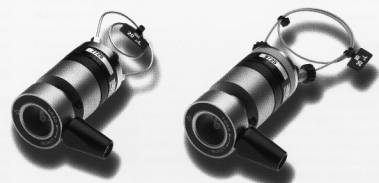
Figure 1. Rheodyne 7725/7725i stainless steel (left) and 9725/97251 PEEK (right) front Iosding sample injection valves for HPLC
Rheodyne 7725/7725i and 9725/ 9725i front loading HPLC Sample Injectors are easy to use, and provide chromatographers with the Rheodyne Hallmark of Excellence... unparalleled performance and exceptional product lifetime.
Patented Make-Before-Break (MBB TM ) architecture virtually eliminates transient pressure shocks for extended column life
Available in stainless steel and PEEK for sample compatibility
Zero sample Ioss
2 µL internal sample loop accessory available
Wide 30° port angles for easy access
Position sensing switch built into "i" models
Small diameter internal flow paths assure minimal dispersion
MBB Flow Design for Pressure Shock Reduction
Rheodyne's exclusive MBB flow architecture virtually eliminates pressure transients. The high pressure flow from the pump is uninterrupted when the injector is switched between LOAD and INJECT, a benefit when using flow sensitive detectors, fragile columns, or pumps that are disturbed by flow or pressure transients.
Fig.2 shows column pressure vs. time for MBB (upper curve) in comparison to non-MBB sample injectors (lower curve).
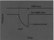
Fig. 2 shows column pressure vs. time for MBB (upper curve) in comparison to non-MBB sample injectors (lower curve).
A passage in the stator face assembly makes new connections before old ones break. This patented Make-Before-Break (MBB) design is an improvement over injectors which use a bypass. lt is easy to troubleshoot, and does not dilute sample.
.
Mechanical Design
The Interface between the rotor and stator face is the location of the flow switching and high-pressure sealing. This Interface is a flat surface, and consists of a rotor seal made of an inert polymer, and a ceramic stator face assembly. The highly-polished ceramic does not scratch or wear under normal use.
As a result, a rotor seal should last for tens of thousands of injections in normal use, and shed very few particles
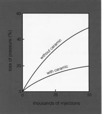
Figure 3. Pressure loss of stainless steel/polymer valve (top) and Rheodyne ceramic/polymer valve (bottom) vs. thousands of injections.
Position Sensing "i" Injectors
In the 7725i and 9725i valves, turning the valve to INJECT closes a built-in position sensing switch, which remains closed until the valve is returned to LOAD. When the position sensing switch wires are attached to a chromatograph, the switch provides the System with a reproducible start signal.
Zero Sample Waste
A syringe needle with a flat end (square cut) must be used. When the needle is inserted into the needle port, the tip of the needle passes through a seal inside the rotor seal, and then contacts the ceramic stator face. This direct connection between the tip of the needle and the end of the loop eliminates sample holdup. All sample leaving the needle enters the loop, so there is zero sample waste.
Leak Tight Needle Seal
The needle seal is a Teflon sleeve that is built into the rotor seal. lt grasps the tip of the needle, aligning it with the loop passage, and assures that all sample dispensed from the syringe enters the loop. The seal is under compression from an internal spring, which maintains a leak-tight, self-adjusting seal around the needle.
Sample Injection
The needle port of each injector is built into the valve's handle. When the injector is mounted an a panel, the handle and needle port are in front (Fig. 4A). In back of the panel are the body and the stator. The stator contains six tubing ports (Fig. 4B) for connecting the pump, column, sample loop, and vent lines.
Fig. 4A shows a cut-away view of the valve in both the LOAD and INJECT positions. Below the cut-away view is an illustration of the internal flow passages. The six circles represent the ports in the stator. The arcs represent the connecting passages in the rotor. The needle port is shown aligned with port 4.
In the LOAD position mobile phase flows to the column via port 2, a rotor passage, and port 3. The loop, which contains mobile phase trapped when the injector was returned to LOAD, can be partially or
completely filled with sample from a syringe via the needle port, which aligns with port 4. The mobile phase displaced by the sample exits the loop via drain at port 6.
With the syringe still in the needle port the valve is turned to clockwise through 60 ° to INJECT. Channels in the rotor seal now directthe mobile phase intotheend opposite from where the sample entered the loop. Note that the sample travels in a direction opposite to the direction during loading; it does not have to pass through the entire loop. The needle port and syringe now align with drain at port 5. When the needle port is flushed, the flushing solvent exits directly out this port without entering the sample loop. The needle port and syringe are never exposed to high pressure. The loop is self-cleaning, being continuously flushed by mobile phase during analysis.
VERSATILE INJECTION METHODS
Rheodyne front loading injection valves operate as follows: Sample is first LOADED into the sample loop by dispensing it from a syringe (Fig. 5) or by pulling it through a dip tube using a Suction Needle Adapter (Fig. 6). Sample is then INJECTED onto the column by turning the handle, which connects the loop to the high-pressure mobile phase stream. These versatile injectors offer a choice of three loading methods: Complete, Partial, and Suction.
Sample Injection using
Complete Filling Method
When injection volumes do not often change, or when sample conservation is not required, complete filling is the method of choice. The complete fill method produces excellent volumetric precision, typically about 0.1% relative standard deviation. Sample is dispensed from a syringe, using an excess amount
(at least 3 times the loop volume) to displace all the mobile phase in the loop. The loop sets the volume injected; the volume is varied by changing the loop size. Since the loop sets the volume, this method does not require precise use of the syringe.
Sample Injection using
Partial Filling Method
Applications where injection volumes change frequently, or when sample conservation is important, partial filling is the method of choice. Volumetric accuracy and precision depend an the operator's ability to read and use the syringe, typically about 1%. The volume injected is determined by the amount dispensed into the loop by the syringe. The amount dispensed must be less than half of the total loop volume. The partial fill method does not waste sample, and allows the volume to be continuously varied without changing the loop.
In partial filling (load no more than 50% of the loop volume), all of the sample dispensed from the syringe needle enters the loop, even with samples as small as 0.1 uL. There is zero sample waste.
Sample Injection using
Suction Method
Rheodyne 9725 (PEEK) valves have no metal in contact with the flow stream. The preceeding methods expose sample to the metal needle of the syringe. Though the exposure is small, metal can be completely avoided by using a syringe to suck sample into the loop via a PEEK tube at port 6. Using this method the tube end is placed into the sample vial. An empty syringe is inserted into the needle port, and used to pull sample into the loop. Model 9125-076 Suction Needle Adapter, an accessory listed under ordering information, is recommended forthe suction method. As shown in Fig. 6, the adapter makes suction loading easier.
SPECIFICATIONS
Stainless Steel Model: 7725 and 7725i
Maximum Pressure: 48 MPa (482 bar, 7000 psi)
Wetted Surfaces: 316 stainless steel, alumina ceramic, and an inert polymer
pH Range: 0-10 (pH >10, contact factory)
Maximum Temperature: 80°C
Flow Passage
Diameters: 0.6 mm (0.024") and 0.5 mm (0.018")


