
Perkin Elmer Integral 4000
| Objektnummer | B00012383 |
|---|---|
| Seriennummer | 012383 |
| Object Naam | Perkin Elmer Integral 4000 |
| Status | Stock unit |
Product groep: HPLC systemen

Status, leverings- en betalingsvoorwaarden
Apparatuurcontrole
De gebruikte apparatuur wordt voorafgaand aan levering gecontroleerd door Labexchange Service GmbH. U ontvangt volledig functionerende apparatuur.
Verzending
De vermelde verzendtijden zijn telkens de kortste voor een artikel. In bepaalde gevallen kunnen de daadwerkelijke verzendtijden daarvan afwijken. De uiteindelijke verzendtijden worden aangegeven in de opdrachtbevestiging.
In de regel bieden we combinatieleveringen aan. Levertijden zijn afhankelijk van het artikel met de langste levertijd. Deelleveringen zijn mogelijk tegen een toeslag.
Verzendmethoden
Koeriersdiensten, transportbedrijven, zelf afhalen, levering door Labexchange wagenpark
Informatie levering
De prijzen zijn exclusief verzendkosten. De genoemde verzendkosten zijn de te verwachten kosten. Afwijkingen zijn mogelijk. In het geval geen kosten voor verzending zijn gespecificeerd, vraag die dan afzonderlijk aan.
De opgegeven vracht- en verpakkingskosten hebben betrekking op de goedkoopste transportroute en zijn onder voorbehoud van onvoorziene kostenstijgingen. Door onvoorziene gebeurtenissen kunnen vrachttarieven en levertijden op elk moment veranderen en moeten ze worden aangepast aan de huidige situatie. Incoterm coderingen volgens Incoterms 2010: Bij afhalen EXW, CFR voor zendingen over zee, CPT per luchtfracht, andere zendingen DAP. Opmerking: We geven geen preferentieel certificaat/EUR1 af. Bij zelf afhalen/af fabriek (EXW) uit derde landen en de EU wordt 16% btw als borg ingehouden, tot we de ontvangstbevestiging/het leveringscertificaat van de koper hebben ontvangen.
Betalingsvoorwaarden
Wij accepteren geen betalingen Letter of Credit, PayPal etc. Het factuurbedrag is volledig verschuldigd. Er zijn geen betalingskortingen. De goederen blijven tot volledige betaling ons eigendom.
|
Land |
Mogelijke betaalmethoden |
Opmerking |
|
Duitsland, Oostenrijk, Zwitserland |
Betaling via factuur, vooruitbetaling, per creditkaart |
Betaling via factuur is mogelijk voor ondernemingsklanten. |
|
Nederland, België en Luxemburg |
Betaling via factuur, vooruitbetaling, per creditkaart |
Betaling via factuur is mogelijk voor ondernemingsklanten. |
|
Andere landen |
vooruitbetaling, per creditkaart |
|
Onze Algemene Voorwaarden voor Verkoop, Levering en Betaling zijn hierop van toepassing. Deze voorwaarden zijn hier te downloaden.
Tussenverkoop is ons voorbehouden.
Beschrijving status:
Alle artikelen zijn gebruikte artikelen, tenzij bij een artikel uitdrukkelijk wordt vermeld dat het om een nieuw apparaat gaat.
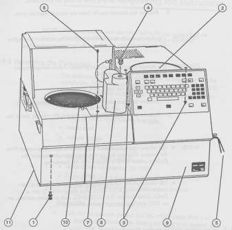
Figure 1 The Locations of the Shipping Screws
① Locking Screw and Washer Secured into Pump Casting
② VDU Platform
③ Captive Detector Shipping Screws
④ Hexagonal Shipping Bolt and Washer
⑤ Caps On Drain Tubes
⑥ Luer Tip Dummy Needle
⑦ Rheodyne Valve Seal (in Position During Shipping)
⑧ Autosampler Arm
⑨ Oven Access Door
⑩ Sample Tray
⑪ Pump Transit Clamp (at rear of pump)
Accessing the Principal Components
The principal components of the Integral 4000 liquid chromatograph are:
Solvent reservoirs and support tray (available as a Solvent Accessory,
part number 1535 0024, which is supplied with instructions for installation and Operation),
Quaternary solvent pump,
Autosampler,
Injection valve,
Oven and column,
Detector.
The left hand side of the instrument, with the Solvent Accessory (L535 0024) fitted. The Solvent Accessory is a seif contained unit that controls the solvent environment and ensures reproducible delivery of solvent. The facility exists to allow thermostatting of the sample tray, by means of an external recirculating water bath (not supplied). The inlet and outlet connections for the cooling medium are also located on the left hand side of the instrument, below the solvent shelf.
The autosampler drains, detector walte lins, mains power on/off switch and the power supply connections panel, where electrical connections are made, are located on the right hand side. The VDU signal connection is located on the left hand side of the instrument.
Accessing the Pump
Verify that the transit clamp has been removed from the back of the pump unit. It is secured on the outside of the pump casting by four screws and is only visible when the pump is removed.
Open the pump access door on the front of the instrument. Disconnect the pipe at the right hand side of the in-line solvent filter, using a 1/2 inch wrench to hold the body of the filter, and a 1/4 inch wrench to loosen the fitting. Open the oven door and spring the pipe into the oven. (lt should not be necessary to disconnect the two Sets of cables from the electronics board on the right.) The pump is secured by two screws and washers. Unscrew these and slide the pump and board forward.
The Autosampler
The sample tray can accommodate up to 100 small vials and 9 large vials; there is also a priority vial position an the instrument, which enables an urgent sample to be given priority over those in the tray.
A sensor detects whether the tray is present and prevents a run from starting if the tray is not located correctly, or if the tray handle is not down.
The sample vial tray may be thermostatted by connection to an external recirculating water bath (for temperatures in the range + 4 to + 40°C), or an ethylene glycol bath (for temperatures in the range -20 to + 4°C).
The Oven and Column
The oven and column are accessed by opening the hinged door an the front of the instrument. The oven can accommodate columns up to 30 cm in length. The use of column clamps (L535 1243) is recommended to retain the tubing in place inside the oven. These are clipped into place either side of the column.
When the oven is in use, the solvent is preheated by passing it through a solvent/sample preheater, where its temperature is raised to the selected value. The Integral 4000 is supplied with the solvent/sample preheater fitted after the injection valve as this gives the better oven performance. Should the user wish to minimize potential problems due to blockages, the tubing may be fitted before the injection valve; it may also be by-passed completely.
Accessing the Detector Flowcell and Lamp
Unclip the keypad panel by pulling it from underneath. The keypad will then hinge down to enable easy access to the detector. The detector flowcell and the metal panel (lamp access panel) above it are shown in Figure 12. Remove the blanking screw from the detector flowcell outlet and connect the waste tubing (L535 1159), which is supplied in the shipping kit.
The lamp access panel is secured by two screws and washers, which must be removed to provide access to the deuterium lamp.
Onze Labexchange-team zullen u graag helpen:

Christian Schmid
Laboratorium en analytiek, Laboratoriuminrichting, Life science

Hubert Sauter
Spectroscopie, Chromatografie


