Appl.Biosystems QSTAR XL PRO
| Objektnummer | B00017822 |
|---|---|
| Seriennummer | 017822 |
| Nome oggetto | Appl.Biosystems QSTAR XL PRO |
| Stato | Archived Product |
Gruppo prodotti: LC / MS
Status, terms of delivery and payment
Verification of devices
The second-hand devices are verified by Labexchange Service GmbH before delivery. You are receiving only fully functional devices.
Dispatch time
The stated dispatch times are the shortest possible ones for each article. The effective dispatch times can vary. The effective dispatch times will be stated in the order confirmation.
As a matter of principle, we are offering collective deliveries. The shipping time is calculated based on the position with the longest lead time. A partial delivery is possible on explicit request.
Shipping methods
Parcel services, forwarding agencies, self-pickup, delivery by Labexchange fleet.
Delivery information
Prices exclude shipping costs. Stated shipping costs are to be expected. Deviations are possible. If transport costs are not specified, please ask separately for them.
The stated transport and packing charges apply to the most favorable route if transport and are to be understood as subject to verification due to unexpected cost increases. By reason of unpredictable events, cargo rates and delivery times can change at any time and therefore have to be adapted to the recent situation. Import formalities and possible customs charges will be borne by the purchaser. Incoterm coding according to Incoterms 2010: For persons who collect the devices themselves: EXW, for dipatch by sea: CFR, by air freight: CPT, other shipments: DAP. Note for international shipments: A proof of preference/EUR1 will not be issued by us. When self-collecting/ordering EXW from countries within or outside the European Union, 16% VAT will be retained as a deposit until we have received the corresponding confirmation of arrival/bill of delivery from the buyer.
Terms of payment
We do not accept payment by letter of credit, PayPal, etc. In each case the invoice amount is payable without deduction. Discount is not granted.
|
Country |
Possible payment methods |
Comment |
|
DE, AT, CH |
Payment by invoice, payment in advance, payment by credit card |
Payment by invoice is only possible for corporate clients. |
|
NL, BE, LU |
Payment by invoice, payment in advance, payment by credit card |
Payment by invoice is only possible for corporate clients |
|
Other countries |
Payment in advance, payment by credit card |
|
Our General Terms of Sale, Delivery and Payment are valid and are available for download here.
The goods are offered subject to prior sale.
Definition of status
All articles are used articles, except an article is listed especially as a new device.
|
Status |
Condition |
Comment |
|
Immediately available |
Used | The article is fully functional and in impeccable condition. It can be shipped immediately. |
| In stock |
Used |
The article is on stock. Our service technicians will verify the article before delivery. You are receiving only a fully functional article. |
|
Published |
Used |
The article is still with the provider. After your order the article will be purchased and verified by us before being shipped to you. A certificate of operativeness as well as a service report are included in delivery. |
|
New device |
new |
The article is brand new and unused. Regarding new equipment the guarantee/warranty conditions of the corresponding manufacturer apply. |
|
Labprocure |
Used |
Labprocure GmbH, as the advertiser, is responsible for the content of this device offer. Labprocure assumes liability for the offers advertised here and for the photos and offer texts included. Labprocure GmbH, Bruckstraße 58, 72393 Burladingen. |
manufacturer : Applied Biosystems
model : QSTAR XL PRO
annotation : Dokumente engl.
The following illustrations and descriptions refer to the instrument model and are drawn from brochures. They do not represent the scope of delivery. Please refer to the text of the offer for the exact scope of delivery.
System Requirements
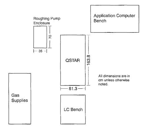
Weights and Dimensions
The mass spectrometer is 81.3 cm (32 in.) Jeep by 163.8 cm (64.5 in.) long hy 135.9 cm (53.5 in.) high. This instrument weighs approximately 591 kg (1300 Ih), excluding the roughing pump.
The roughing pump should be located behind or beside the AP1 QSTAR® instrument and should always be used in the sound damping enclosure that is provided. The roughing pump weighs approximately 35 kg (77 1b). The sound damping enclosure is 35 cm
(13.8 in.) wide hy 70 cm (27.6 in.) long by 55 cm (21.7 in.) high.
Room Dimensions
The customer must provide the Customer Service Representative adequate access to the instrument. Provisions should be made for clearance of approximately 1 m (3.3 ft) to any side and 1.2 m (4 ft) to the rear of the unit at the time of service.
Suggested Room Layout
While the recommendations for room layout are flexible, the recommendations regarding operating conditions should be followed as closely as possible to ensure proper and safe equipment operation.
Suggested room layout for API QSTAR instrument without oMALDI-top view
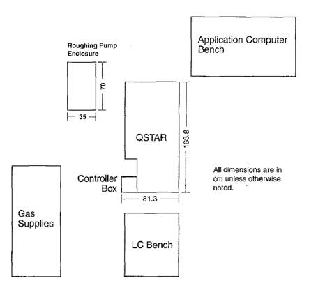
Suggested room layout for API OSTAR Instrument with oMALDItop view
The LC pumps and autosamplers require a movable bench for access to the IonSpray S ource.
Computer equipment may be placed an a fixed bench, provided that access to the Instrument is not restricted. The computer bench must be located within 3 m (10 ft) of the instrument.The bench space requirements for the pumps, computers, and other accessories is dependent an the respective manufacturer.
Operating Environment
The operating environment should be kept clean and generally dust-free.
Mass Spectrometer
To ensure the proper operating conditions for the instrument, the environmental conditions must be maintained between 18 °C and 25 °C (59 °F to 77 °F) ±1 °C (2 °F) with a relative humidity of between 20 and 80% non-condensing. Operation of the instrument at greater than 2000 m above sea Ievel is not recommended.
The basic API QSTAR® system air conditioning requirements are 4400W (15 020 Btu/h) for the mass spectrometer and roughing pump.
Roughing Pump
To ensure proper operation of the roughing pump, the ambient temperature must he maintained between 18 °C and 45 °C (65 °F to 110 °F), with a relative humidity of 20 to 80% non-conclensing.
CAUTION! lt is important that the roug hing pump enclosure be properly ventilated. Without proper ventilation the pump will fall prematurely or shut down from overheating, which can cause significant damage to the mass spectrometer.
Electrical Requirements
A 207 to 242 VAC 50/60 Hz, 30A grounded, single phase circuit with one receptacle should be used to supply the power requirements for the API QSTAR instrument. The required receptacle is an IEC 309, 32A, 3 pin, 230 VAC receptacle. It must be located within 1.8 m (6 ft) of the instrument.
NOTE: Applied Biosystems/MDS SCIEX does not recommend or specify powerline conditioners. See "Appendix A" for a discussion of power conditioner requirements.
A minimum of three electrical outlets are required for the computer equipment. Consult the respective manufacturer's documentation for specifications.
Other outlets will be required for the data acquisition workstation, LC pumps, autosamplers, ADC Boxes and UV detectors. The respective manufacturer's specifications should contain this information.
If the Peak Scientific gas generator option has been purchased, refer to "Appendix C" for its electrical requirements.
Power Consumption
The API QSTAR instrument, including the roughing pump, will consume 20A (4400 W).
Gas Requirements
The API QSTAR instrument requires several types of input gas, and the purity and pressures stated below should be adhered to for proper operation of the instrument. The stated gas purities are those required at the instrument.
For regulator and gas fitting requirements, see the "Customer Supplied Requirements" section, later in this guide.
Gas 1 and Gas 2
Zero air or UHP (99.999%) nitrogen, or approved nitrogen gas generators with impurities that are known not to negatively impact performance, at a maximum of 105 psig and flows up to 12 L/min is required.
Curtain Gas and Vent Gas
UHP nitrogen (99.999%), or approved nitrogen gas generators with impurities that are known not to negatively impact performance, at a maximum of 60 psig and flows up to 4 L/min is required.
CAD Gas
Without the oMALDI sources, the QSTAR series of Instruments require UHP nitrogen (or approved nitrogen gas generators with impurities that are known not to negatively impact perfortnance) at a maximum pressure of 60 psig and flows up to 1 L/min. The QSTAR Pulsar 1 or XL with oMALDI sources require UHP (99.999%) argon at a maximum of
60 psig and a flow rate of up to 1 L/min.
Source Exhaust Gas
Clean, dry, and oil free air at maximum 50 psig at flows up to 8 L/min is required. Alternatively, clean nitrogen may be used instead of air.
Gas Requirements
|
Component |
Gas |
Delivery psig (max) |
Gas Purity |
Flow (max) |
|
Gas 1 and 2 |
Air or nitrogen |
105 psig |
Zero air or UHP N 2 (99.999%)* |
12 L/min |
|
Curtain and Vent |
Nitrogen |
60 psig |
UHP N 2 (99.999%)* |
4 L/min |
|
CAD gas |
QSTAR Series without oMALDI source |
|||
|
Nitrogen |
60 psig |
UHP N 2 (99.999%)* |
1 L/min |
|
|
QSTAR Pulsar i or XL with oMALDI sources |
||||
|
Argon |
60 psig |
UHP Ar (99.999%) |
1 L/min |
|
|
Source exhaust |
Air or Nitrogen |
50 psig |
Clean, dry and oil free |
8 L/min |
* or approved nitrogen gas generators with impurities known not to negatively impact performance
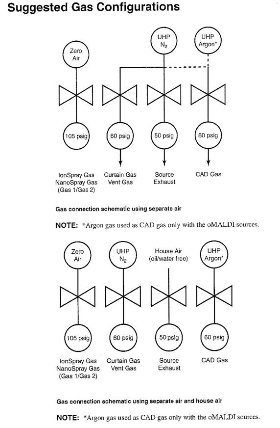
CAUTION! If house gases are being supplied, each supply must be separately regulated at the Instrument because gas requirements vary according to the type of gas input. Othervtrise, the valves inside the Instrument may be damaged by over pressure.
Gas Connection Panel
The Gas Connection panel is Iocated an the back of the instrument.
The preferred method for gas line connections is the use of compression fittings. Liquid pipe sealant is not acceptable for gas line connections. If threaded fittings must be used, only Teflon tape is acceptable for sealing the threads. Soldered fittings are not acceptable unless the tubing is thoroughly cleaned.
Exhaust Requirements
Exhaust from the API QSTAR instrument comes from the source exhaust and roughing pump. See the warning below for source exhaust safety issues.
Source Exhaust Pump
During operation, solvent vapors am exhausted from the ion source by the source exhaust pump to a 1.27 cm (0.50 in.) barbed fitting at the rear of the instrument. These vapors pass through a source exhaust bottle that is supplied with the instrument, which then must be vented to a fume hood or outside port. The diameter of the source exhaust bottle exhaust port is 1.27 cm (0.50 in.).
Roughing Pump Exhaust
You have the option of purchasing the installation kit, which includes smoke eliminators (mist filtern) for the roughing pump. If the pump exhausts to a fume hood er an outside source, a positive flow vent with a 3.2 cm (1.25 in.) OD smooth fitting is required. The system includes fittings and tubing to tonnett the roughing pump to a fume hood or vent located within 1.5 m (5 ft) of the instrument.
WARNING! lt is required that the source exhaust system be used and that the
exhaust is safely removed from the laboratory environment.
WARNING! Use qualified personnel for the installation of plumbing and fixtures, and ensure that all installations follow local bylaws and biohazardous regulations.
Data Acquisition Workstation Requirements
The customer is strongly advised to purchase the data acquisition workstation from Applied Biosystems/MDS SC1EX.
Computer system requirements may be updated from time to time. Please contact your service representative for current system requirements.
The customer is responsible for establishing EtherNet network connections and assigning a unique TCP/IP address to the applications computer. The Applied Biosystems Customer Service Representative will provide the information required to tonnett the API QSTAR system to the data acquisition workstation. You will need to contact your Systems
Customer Supplied Requirements
The customer is responsible for providing the following supplies while operating the API QSTAR© instrument.
Solvents
The customer supplies methanol, acetonitrile, and water (all HPLC grade).
Gases
The customer supplies the following gases:
Zero air or tile, nitrogen at maximum of 105 psig, up to 12 L/min for Gas 1 and Gas 2
UHP nitrogen at maximum of 60 psig, up to 4 L/min for Curtain gas and Vent gas
UHP nitrogen at maximum of 60 psig, up to 1 L/min for CAD gas
UHP argon at maximum of 60 psig, up to 1 L/min for CAD gas (for API QSTAR Pulsar i or XL with oMALDI sources only)
House air or nitrogen at maximum of 50 psig, up to 8 L/min for source exhaust pump
WARNING! Use qualified personnel for the installation of plumbing and fixtures, and ensure that all installations follow local bylaws and biohazardous regulations.
Regulators
The customer supplies the appropriate gas regulators for the gas supplies. The gas regulators required for cylinders and dewars or for house gases are listed in the "Suggested Gas Configurations" section.
Electrical
The customer supplies the following electrical connections:
One grounded 207 to 242 VAC, 50/60 Hz, single phase, 30A circuit with one IEC 309, 32A, 3 pin, 230 VAC receptacle for the API instrument and roughing pump. The receptacle raust be located within 1.8 in (6 ft) of the instrument.
NOTE: Applied Biosystems/MDS SCIEX does not recommend or specify powerline conditioners. See "Appendix A" for a discussion of power conditioner requirements.
Sufficient outlets for autosamplers, LC pumps, and data acquisition workstation. See manufacturers" specifications for voltage, current, and other requirements.
WARNING! Use qualified personnel for the Installation of all electrical fixtures, and . , ensure that all installations follow local by-laws.
Ventilation
The customer supplies ventilation as required by local bylaws and regulations for the roughing and source exhaust pumps. The maximum pump flow is less than 8 L/m in.
Part numbers for roughing pump smoke elim inators and exhaust hosing are given in the table below. Two 1.5 m (5 ft) lengths of exhaust gas hole and fittings are supplied with the system. Exhaust lines greater than 1.5 m (5 ft) will require extra tubing and tittings. With the optional smoke eliminator kit (WC014543), roughing pump venting is not necessary.
The source exhaust pump regulator fitting is a 1/4 in. NPT to 1/4 in. Swagelok Fitting (Swagelok P/N SS-400-11-4). Porting for the remaining regulators are 1/4 in. NPT fittings (female). The regulator outputs require 1/4 in. NPT to 1/8 in. Swagelok fittings (Swagelok P/N SS-200-11-4). You will also need to supply sufficient 1.27 cm (0.5 in.) ID silicone tubing to connect the source exhaust bottle to the ventilation point.
WARNING! lt is required that the source exhaust system be used and that the
exhaust is safely removed from the laboratory environment.
WARNING! Use qualified personnel for the Installation of plumbing and fixtures, and ensure that all installations follow local bylaws and biohazardous regulations.
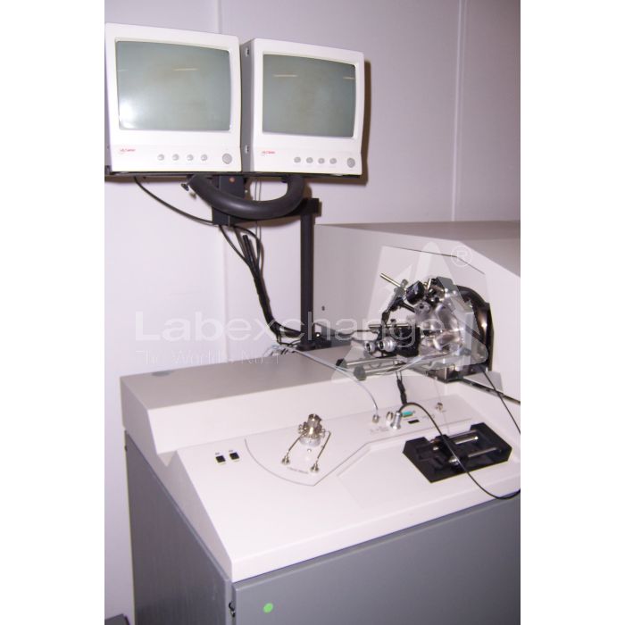
Nano Spray Source
Why Use This Source?
The NanoSpray source extends the versatility of the QSTAR ion source techniques to allow lower sample flow rates with high sensitivity for
automated capillary LC/MS/MS applications using the Continuons NanoSprayTM and MicroIonSpray") heads.
In nanospray applications, an electrical potential is applied to the sample as it passes through a stainless steel union and then into a fine-tipped emitter needle. The sample is ionized by ion evaporation, and the resulting ions enter the mass spectrometer for filtering and detection. To use the NanoSpray source, you raust replace the standard QSTAR curtain plate with a new curtain plate designed to bring the emitter tip into closer proximity to the orifice plate hole for improved transmission of ions. The NanoSpray source operates with a minimal curtain gas setting, and is not recommended for higher flow rates that require curtain gas to ensure betten declustering.
As a "soft" ionization technique, nanospray is particularly useful for analyzing biological samples such as proteins while using very small sample amounts. With the Continuous NanoSpray and MicrolonSpray heads, you can also Lake full advantage of capillary chromatography.
The Continuous NanoSpray head accommodates low sample flows from 10 to 500 nL/min of different solvent compositions, and is ideally suited for analysis of complex samples using capillary LC systems. The Continuous NanoSpray is also convertible to a Discrete NanoSprayTM with flow rates from 20 to 40 nL/min when analysis of a single sample over a period of time is required. The MicrolonSpray head accommodates samples from 10 to 1000 nL/min with very low sample consumption.
Features of the NanoSpray Source
The NanoSpray source has the following features:
- Near 100% sample utilization.
- Minimal sample requirement.
- High sensitivity, as the ionization technique results in fine droplets for ionization.
- Ease of installation and exchange for other ion sources with the QSTAR series of instruments.
- CCTV monitors for positioning the emitter accurately and for observing spray.
Continuous NanoSpray Head Features
Sorne of the features of the Continuous NanoSpray head include the following:
- Functions with flow rates from 10 to 500 nL/min.
- Interfaces to any liquid chromatography system.
Discrete NanoSpray Head Features
Some of the features of the Discrete NanoSpray head include the following:
- Functions with flow rates from 20 to 40 nL/min.
- Ahle to analyze a srnall sample over long periods of time.
- Low sample consumption.
MicrolonSpray Head Features
Some of the features of the MicrolonSpray head include the following:
-
Able to function with flow rates from 10 to 1000 nL/min depending on
the internal diameter (2 to 50 nm) of the fused silica tubing used. - Ahle to ionize 100% aqueous to 100% organic solvents.
- Positive and negative ion mode analyses.
- High sensitivity for biological compounds.
- Formation of molecular Ions with no thermal degradation.
- Allows ionization of compounds in the kilodalton mass range.
- Very low sample consumption.
- Interfaces to any liquid chromatography system.
NanoSpray Source Component
Overview
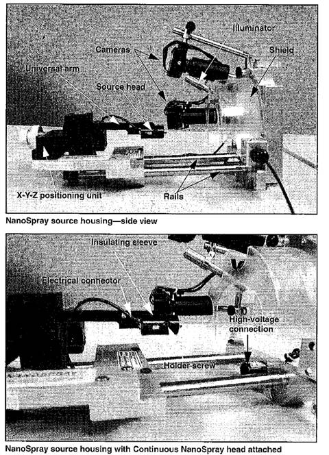
The main components of the NanoSpray source include the following:
- Source frame with cover and brackets.
- Three source heads.
- Two cameras for viewing the spray, with accompanying monitors.
- One illuminator.
- Rails on which the source moves forward and back.
- x-y-z positioning unit with knobs for adjustment of the emitter tip relative to the curtain plate.
The NanoSpray source frame includes brackets for the cameras and the illuininator attachment. The source frame also supports the rails and x-y-z positioning unit. For more information, see the following figure, NanoSpray source housingside view.
NanoSpray source housingfront view
For the Continuous NanoSpray head, the universal arm Nolds the source head into which you insert the union joining the fused silica or LC column and the emitter tip. Electrical connection for the spray voltalte is made from the instrument to the union holder on the spray arm and thus the union, placing a potential on the sample.
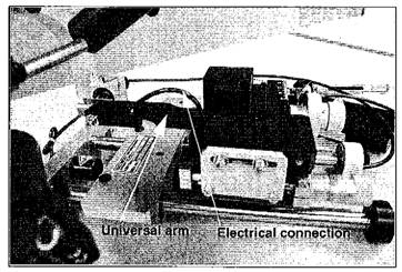
The Discrete NanoSpray is held in place by an adapter attached to the universal arm, while the MicrolonSpray head attaches directly to the universal arm. Electrical connection for the spray voltage is made from the instrument to the top of the source heads.
When the source head is pulled back from the instrument, the high voltage to the head is disconnected. To engage the high voltage, the positioning unit must slide completely into place against the source housing.
CAUTION: To avoid damaging the tip, when sliding the positioning unit toward the curtain plate with an emitter tip in place, ensure that you have first used the x-y-z knobs to slide the x-y-z positioning unit as far away from the Instrument as possible to avoid striking the tip an the curtain plate.
Flow Types and Emitter Tips
WARNING! Always wear safety glasses when working with emitter tips, and follow all safety precautions and procedures recommended in the manufacturer's documentation.
Selection of flow type and emitter tips is dependent upon your application.
Discrete NanoSpray results in betten quality data when scanning an a
particular ion or making extensive study of one protein in very small amounts. Continuous NanoSpray with LC pre-separation gives best results for complex samples, such as protein digests where you are interested in all peptides.
Emitter tips can be uncoated or either distaf- or proximal-coated with a conductive material that transmits the charge to the liquid passing through the tip, faciIitating ion evaporation.
Uncoated and Coated Fused Silica Emitter Tips
Emitter tips can be uncoated or coated with a conductive material to facilitate ionization of the sample passing through the Union and tip. If coated tips are used, distal-coated tips are suggested; the tips are coated on pari of the needle but not at the outlet end. (Proximal-coated tips are coated on the outlet end.)
The emitter tip is seated in a PEEK sleeve inside the conductive ferrule and Valco union supplied with the ion source. Electrical connection to the union is supplied to the source head from the mass spectrometer.
WARNING! The NanoSpray source needle is very sharp. Extra care should be used when handling the needle to avoid injury. Used needles shall be disposed of in an appropriate "sharps" or similar container that renders them inaccessible.
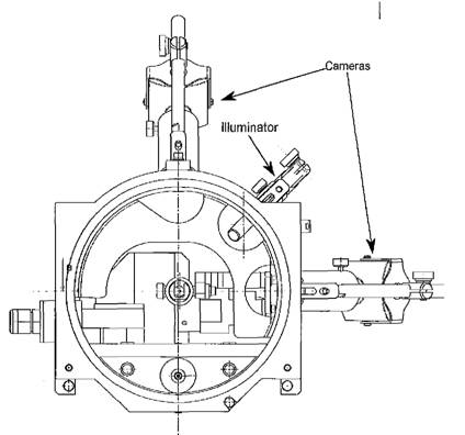
Cameras
Two cameras focused on the emitter tip and curtain plate hole allow you to view the NanoSpray operation. The cameras are inounted in brackets on the source housing, and can be adjusted for proximity, direction, and focus. Two monitors Show the camera outputs.
Illuminator
A single illuminator provides light for observing the orifice and tip.
Rails
The source head positioning unit can be pulled back along the rails to provide access to the heads. The unit raust be pushed completely into position against the source housing to properly engage the high voltage. Once the unit is in
place against the source housing, the location of the emitter tip can be adjusted using knobs on the x-y-z positioning unit.
![]() CAUTION! To avoid damaging the tip, when sliding the positioning unit toward the curtain plate with an emitter tip in place, ensure that you have first used the x-y-z knobs to slide the
CAUTION! To avoid damaging the tip, when sliding the positioning unit toward the curtain plate with an emitter tip in place, ensure that you have first used the x-y-z knobs to slide the
x-y-z positioning unit as far away from the Instrument as possible to avoid striking the tip on the curtain plate.
When the unit is pulled back along the rails from the source housing, the electrical high-voltage is disengaged, shutting off power to the source head.
X-Y-Z Positioning Unit with Adjustment Knobs
The source head moves in relation to the curtain plate hole through adjustments to the x-y-z positioning unit's adjustment knobs.
The adjustment knobs provide the following controls:
- Fine movement toward and away from the curtain plate.
- Coarse movement toward and away from the curtain plate.
- Vertical movement.
- Horizontal movement.
CAUTION! To avoid damaging the tip, when sliding the positioning unit toward the curtain plate with an emitter tip in place, ensure that you have first used the x-y-z knobs to slide the x-y-z positioning unit as far away from the instrument as possible to avoid striking the tip an the curtain plate.
Il tuo Labexchange-Team sarà lieto di aiutarvi:

Christian Schmid
Laboratory and analysis, Laboratory equipment, Life science

Hubert Sauter
Spectroscopy, Chromatography


