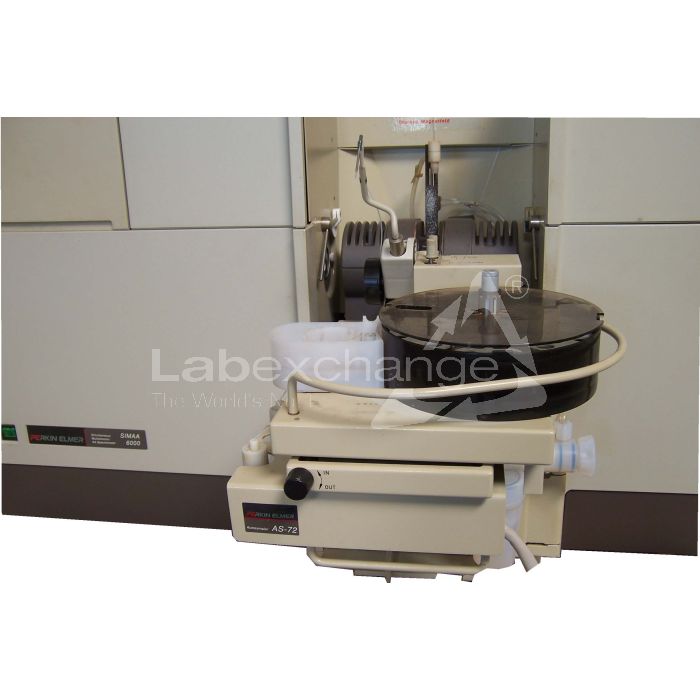
Perkin Elmer SimAA 6000
| Objektnummer | B00014048 |
|---|---|
| Numéro d'identification | 014048 |
| Nom de l'objet | Perkin Elmer SimAA 6000 |
| Statut | Stock unit |
Groupe de produits: Absorption atomique (graphite tube)
Statut, conditions de livraison et de paiement
Vérification des appareils
Les appareils d’occasion sont vérifiés par Labexchange Service GmbH avant la livraison. Vous recevez des appareils entièrement fonctionnels.
Délai d'expédition
Les délais de livraison indiqués sont les plus rapides pour l’article en cause. Les délais de fait peuvent varier au cas par cas. Les délais de livraison définitifs sont indiqués dans la confirmation de commande.
Nous offrons des livraisons collectives par principe. Le délai de livraison s’oriente à l’article avec le délai de livraison le plus long. Une livraison partielle est possible par prix additionnel.
Méthodes d'expédition
Courrier, agences d'expédition, autocueillette, livraison par flotte de Labexchange
Conditions de livraison
Prix plus frais d’expédition. Les frais d’expédition indiqués sont à prévoir. Dérogations éventuelles sont possibles.
Si les coûts de transport ne sont pas spécifiés, s'il vous plaît demander séparément les frais de transport. Les frais de transport et d'emballage indiqués se réfèrent à l'itinéraire de transport le moins cher et sont sujets à des augmentations de coûts imprévues. En raison d'événements imprévisibles, les tarifs de transport et les délais de livraison peuvent changer à tout moment et doivent être adaptés à la situation actuelle. Incoterm codage selon les Incoterms 2010: Pour personnes qui viennent chercher les dispositifs elles-mêmes: EXW, pour les expéditions par voie maritime: CFR, par avion: CPT, d'autres expéditions: DAP. Remarque: Nous n'établissons pas des preuves préférentielles/EUR1. Dans le cas d’un enlèvement par vos soins/EXW de pays à l’intérieur ou à l’extérieur de la Union européenne, nous devons conserver 16% de TVA d’acheteur comme dépôt de garantie, jusqu’à ce que nous ayons reçu l’attestation de reception/la prevue de livraison.
Modalités de paiement
Nous n’acceptons pas le paiement par lettre de credit, PayPal, etc. Dans tous les cas le montant est payable sans déduction. Jusqu’au paiement complèt l’équipement reste notre propriété. Un escompte n’est pas accordé.
|
Pays |
Modalités de paiement possible |
Remarque |
|
DE, AT, CH |
Paiement par facture, prépaiement, par carte de credit |
Paiement par facture est possible pour clients professionnels. |
|
NL, BE, LU |
Paiement par facture, prépaiement, par carte de credit |
Paiement par facture est possible pour clients professionnels. |
|
Autre pays |
Prépaiement, par carte de credit |
|
Nos conditions de vente, de livraison et de paiement sont en vigueur. Vous pouvez télécharger les documents ici.
La vente intermédiaire nous est réservée.
Défintion des statuts
Tous articles sont d’occasion, sauf si explicitement défini comme « appareil neuf ».
|
Statut |
Condition |
Remarque |
|
Immédiatement disponible |
Occasion |
L’article a été déjà entièrement vérifié et peut être envoyé directement à vous. |
| En stock |
Occasion |
L'article est en notre stock, mais doit être vérifié avant la livraison par nos techniciens Vous recevez des articles entièrement fonctionnels. |
|
Publié |
Occasion |
L’article est toujours au l’offreur. Nous achetons, vérifions et en fin livrons l’article après votre commande. Le certificat de fonctionnement ainsi que le rapport de service sont inclus à la livraison. |
|
Appareil neuf |
Neuf |
C’est un dispositif neuf. L’article n’est pas utilisé et neuf d’usine. En ce qui concerne des article neufs, la garantie du fabricant est valable. |
|
Labprocure |
Occasion |
Responsable du contenu de l‘offre d’appareil est la société Labprocure GmbH, comme annonceur. Labprocure assume la responsabilité des offres annoncées ici ainsi que des photos et des textes d’offre inclus. Labprocure GmbH, Bruckstraße 58, 72393 Burladingen. |
Firma: Perkin Elmer
The following illustrations and descriptions are referring to the instrument model and are drawn from brochures. They are not representing the delivery volume. The exact delivery content you will find only in the offering text.
The SIMAA 6000 Spectrometer System
Concept
The SIMAA 6000 spectrometer from Perkin-Elmer is a high performance atomic absorption spectrometer, specially designed for simultaneous, multi-element, graphite furnace analyses. It is capable of fully automatic, single or multi-element analyses. The spectrometer and atomizer control, and the display and manipulation of data are all performed through the Computer.
Features of the SIMAA 6000 System
Automated simultaneous determination of up to six elements.
Single path, AC modulated, high efficiency optical system.
Inverse longitudinal Zeeman-effect background correction system with AC modulated magnetic field.
The combination of the optical design and background correction system produce an ideal double-beam system.
Transversely heated furnace with accurate temperature control for Optimum analytical reliability and reduction of interferences.
A flexible and accurate autosampler that can automatically prepare solutions from stock solutions and perform multiple pipetting while the previous analysis is still in progress.
Easy to use AA WinLab software that you use to control almost all Instrument functions. It includes a range of powerful, flexible quality control functions.
Background correction is performed at exactly the saure wavelength as absorbance measurements. Almost complete elimination of all interferences caused by background effects, including structured background effects.
Accurate compensation and elimination of high background levels for all elements, without the need for additional deuterium lamp background compensation.
System components
The SIMAA 6000 system is a Compact benchtop spectrometer. The major components of the system are:
The spectrometer unit itself, containing the optics; including lamps and polychromator, the electronics and the furnace compartment.
The graphite furnace in the furnace compartment and the components associated wich the furnace:
4 The fume extraction unit.
4 The furnace autosampler, mounted on the door of the furnace compartment.
The furnace cooling system.
The computer and associated software, AA WinLabTM,
The printer which is optional but recommended.
System control
To control the spectrometer and perform your analyses you use the AA WinLab applications program which runs under Windows. The computer keyboard, the screen and the mouse form the user Interface.
When you switch on the spectrometer, the system performs an initialization procedure to check the Instrument. While the spectrometer is operating, the control system continually monitors mang instrumental functions. lt produces appropriate messages rohen a problem occurs and prevents potentially dangerous situations occurring.
For more Information about the application program and how to use it to perform analyses, See the handbook: Setting Up and PerformingAnalyses, the online help and the software guide.

The Spectrometer
The Optical System
Layout and Design
A single-path optical system is used in the SIMAA 6000 spectrometer. Front-surfaced, reflecting optical components are used; the only exception being the dispersing prism. The mirror surfaces haue a protective coating of silica.
The inverse longitudinal Zeeman-effect is used for background correction. This has the advantage that no polarizer is necessary. The combination of the optical design and the background correction system produce an ideal double-beam system with the high intensity of a single-path system.
Since the magnetic field acts on the atomized sample, simple live source lamps can be used. Botte the lamps and the magnetic field are modulated and controlled by the spectrometer.
See page 3-37 for a description of the background correction system.
Polychromator
An Erhelle polychromator with a patented tetrahedral mount produces a two-dimensional Image on the detector. This enables mang Signals to be measured simultaneously.
The design of the polychromator eliminates spherical aberration and astigmatism.
The camera mirror can be slewed to put any wavelength between 190 nm and 900 nm on one of the detector Biodes. This allows the polychromator to be used as a monochromator.
Detector
The detector is a solid-state two-dimensional diode array with sixty, independently controlled phododiodes. The detector is connected to eight, parallel, Signal-processing channels.

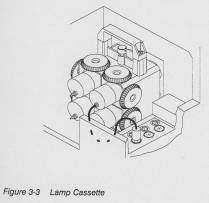
Lamps
The lamp cassette Nolds four lamps. These can be single-element or multi-element hollow cathode lamps (HCLs) or electrodeless discharge lamps (EDLs).
The lamps are live sources and provide the element-specific radiation that is used for the absorption measurements. The lamp current is modulated by the spectrometer; see page 3-34. The lamp cassettes are removable. You may have mang lamp cassettes containing particular combinations of lamps. When you change a lamp cassette you do not usually have to realign the lamps.
You can use the radiation from either one, two or four of the lamps in the cassette. You select this in the AA WinLab application. The radiation beams from two or four lamps are combined wich either a two-faceted mirror or a four-faceted mirror respectively. If only one lamp is used, a plane mirror directs the radiation beam into the optical System.
The Electrical Connections and Switches
On/Off Switches

The cooling system is supplied with power (single phase, 230 V) by the spectrometer. A special Gable is supplied with the spectrometer for this purpose. Do not connect the cooling system to an external power supply.
You can leave the cooling system switched on, since it is controlled by the spectrometer.
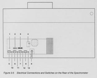
Connections and Controls an the Rear Panel
Pos. Label Function
1 Ethernet Socket for the ethernet cable.
2 IEEE Socket for the IEEE-488 bus cable connecting the spectrometer to the
computer.
3 Instrument A special Interface socket for service purposes.
4 Furnace Power Circuit breaker switch for the furnace. A safety device should the furnace
start
taking too muck current.
5 Printer Power supply outlet for a printer 230 V (AC) 50/60 Hz
6 Monitor Power supply outlet for a monitor. 230 V (AC) 50/60 Hz
7 Computer Power supply outlet for a computer. 230 V (AC) 50/60 Hz
8 Cooling Power supply outlet for the cooling System.
System Only connect the cooling system to this socket
230 V (AC) 50/60 Hz using the cable provided. Do not connect the cooling system to any
other supply.
9 --- Permanent power supply cable for the complete system.
Fitted with either a 5 pole CENELEC connector for 400 V, 32 A, 3 phase,
or a 3 pole NEMA connector rated for 250 V, 30 A.
10 Si 3 Fuse for the printer power outlet.
11 Si 4 Fuse for the monitor power outlet.
12 Si 5 Fuse for the computer power outlet.
13 Si 1 Fuse for cooling system power outlet.
The Graphite Fumace
Design
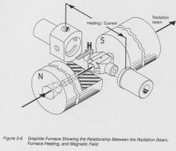
The SIMAA 6000 uses a transversely heated graphite furnace. The furnace is electrically heated. The voltage is applied across the graphite tube, perpendicular to the radiation beam.
The background correction system uses the inverse, longitudinal Zeeman-effect. The magnetic field is orientated parallel to the radiation beam and acts on the atomized sample.
The furnace is mounted on a baseplate in the furnace compartment of the spectrometer. You can pull the furnace forward, out of the radiation beam, to perform maintenance on the furnace. This does not affect the alignment of the furnace relative to the radiation beam. The furnace is aligned at the factory, and checked by the Service engineer during the initial Installation. You can realign the furnace, although this is not usually necessary.
You open and close the furnace using a Software command to activate the pneumatic system. With the pneumatic pressure released, you can open the furnace by hand.
Even when the spectrometer is switched off, the furnace is held closed if there is pressure in the gas supply live. If you release the pressure in the lines you can open the furnace.
The Graphite Tube and contacts
The special graphite tube is held in position in the furnace by two contacts. These provide the electrical contacts for the heating. The contact surfaces must be perfectly clean and smooth to allow consistent heating conditions.
You must periodically clean the contact surfaces and change the contacts when necessary.
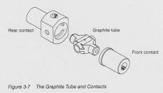
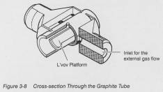
The graphite tube with its integral Evov platform is made from a single piece of electrographite with a coating of pyrolytic graphite. The tube has precisely engineered holes for the external gas flow; see page 3-20.
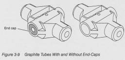
The end-caps are also made from electrographite with a coating of pyrolytic graphite.
The Evov platform enables the Sample and graphite tube to be in thermal equilibrium during the atomization step. This is an important requirement of the STPF concept (Stabilized Temperature Platform Furnace).
Tubes wich and without end-caps are available. The end caps prevent the atomized sample from dispersing too quickly. For some applications this can be very useful.
Fumace Heating and Temperature Profile
The furnace is electrically heated. A low-voltage high-current supply is applied across the graphite tube, perpendicular to the path of the radiation beam through the tube. The front and rear contacts provide the electrical contacts.

The transverse heating provides a more uniform temperature profile within the tube than longitudinal designs. There are no cooler parts of the tube where atoms can recombine, condense, or interact with cooler matrix components during the atomization step. The design has a number of advantages compared with conventional designs:
The efficiency of atomization is increased there is a greater concentration of atoms in the radiation beam.
Less tailing of the analyte absorption signal.
Reduced background absorption.
A major reduction of carryover and memory effects, which can be especially important for multi-element analyses.
Determinations of refractory elements require shorter heating times.
Maximum Power Heating
This produces the most rapid heating of the tube and atomization of the sample. The heating rate is approximately 2000 'C/s. It is recommended for most analyses and is an important component of the STPF concept.
To select this method of heating, you enter 0 (zero) for the Ramp Time in the atomization step of the furnace program.
Time-Controlled Heating
Time-controlled heating is usually used for program steps other than the atomization step except in special situations.
To select this method of heating, you enter a time between 1 and 99 (seconds) for the Ramp Time in the relevant furnace program step. The heating rate is always lower than the maximum power heating rate.
Temperature Control
The temperature regulation System of the SIMAA 6000 continually monitors the effective voltage across the tube and uses this together wich the initial and final temperatures to control the heating. During maximum power heating, the emission temperature of the tube, measured by an optical Sensor in the rear contact housing is also used to control the heating.
The Fumace Gas System
Principle of the Gas Flushing System
During graphite furnace analyses an inert gas atmosphere inside the graphite tube is essential to prevent the sample being oxidized during the atomization step. The inert gas is also used inside and around the outside of the graphite tube to prevent the tube being oxidized at high temperatures and to fluch vapors and fumes out of the tube.
The furnace gas system supplies two independently controlled flows, the external and infernal flows. These are described in more detail an page 3-22
The furnace gas system has two inlets; the Normal Gas inlet and the Special Gas inlet, to allow you to connect two separate gas supplies to the furnace. The Normal Gas inlet provides:
The inert gas that prevents the graphite tube and sample oxidizing at high furnace temperatures.
The pneumatic pressure that Nolds the furnace closed and ensures that the graphite tube makes good electrical contact with the contacts.
The pneumatic pressure that moves the nozzle of the fume extraction unit.
The Special Gas inlet supplies the furnace with a Special gas during some steps of a furnace program. This is optional but is useful for particular applications, for example, air may produce more effective ashing of organic materials.
The connectors for the gases are behind the panel at the front right-hand side of the spectrometer.
Note: The furnace will operate correctly only if there is gas pressure at both gas inlets. If you are using only an inert gas you must connect the gas to both inlets using the Y-connector provided.
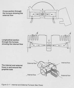
The External Gas Flow
The external gas flow protects the outside of the graphite tube from being oxidized when the graphite tube is heated. Usually argon is used. The gas enters the furnace through the rear of both contacts and flows into the spare between these and the graphite tube. It flows over the outside of the graphite tube and exits through the sample injection hole in the rear contact and through the gap between the two contacts.
The external gas flow, 2 x 100 mL/minute, starts when the spectrometer is switched an and stops automatically when the furnace has been idle for 10 minutes. During a furnace program the external gas flows continuously.
The Internat Gas Flow
The internal gas flow enters the graphite tube at both ends and exits through the sample injection hole. The flow starts as soon as you Start a furnace program and stops automatically when the furnace has been idle for 10 minutes.
Usually an inert gas, argon, is used to protect both the inside of the graphite tube and the sample from being oxidized. The internal flow also flushes vapors and fumes, produced during the pyrolysis steps, out of the tube.
You ran also use a special gas for the internal gas flow. This is optional but is useful for particular applications. For example, air may produce more effective ashing of organic materials.
For each step of the furnace program you raust select either the inert gas or the special gas and one of three possible flows:
2 x 250 mL/min
2 x 50 mL/min
0 mL/min
The flow values are valid for argon. lf you use nitrogen they will differ slightly from the values quoted.
During each step of the furnace program the gas flows at the rate specified for that step. For any step where you specify a lower flow than that for the previous step, the system reduces the flow five seconds before the step starts. This ensures that the flow is stable when the step starts.
Selecting zero flow for the atomization step ensures that the graphite tube and sample are in thermal equilibrium; an important requirement of the STPF concept.
Inert Gas
Argon is the recommended inert gas. It does not react with either the graphite tube or the sample at the temperatures used in the furnace.
Nitrogen is not recommended as an inert gas for the furnace. It can react both with the graphite tube and samples at normal atomization temperatures. Nitrogen does not provide such efficient protection for the graphite tube as argon at temperatures above 2000°C and can react with the graphite tube to form toxic cyanogen gas (CN)2 at temperatures above 2300'C.
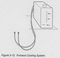
The Fumace Cooling System
For rapid and accurate temperature control, the furnace raust be both cooled and heated.
Cooling is achieved using water flowing through tubes that are integrated into the furnace, The furnace can be cooled in 20 seconds from its maximum temperature to that of the incoming cooling water.
A sensor monitors the temperature at the water inlet to the furnace and shuts the furnace down if the temperature rises above 90 °C.
Perkin-Elmer provides a recirculating cooling system wich the furnace. It provides coolant at a constant temperature and flow, to allow the most reproducible analytical conditions. It also makes the system independent of external water supplies, saves water, and saves energy since it shuts down automatically if the furnace has been idle for more than 10 minutes.
The cooling system uses a 1:10 solution of glycerine in deionized water or Sediment-free drinking water.
The Fume Extraction Unit
Principie
During the thermal pretreatment steps of a furnace program, fumes ran be produced which are often acidic or corrosive and may be toxic. The fume extraction unit for the SIMAA 6000 spectrometer extracts these fumes immediately as they are flushed out of the graphite tube by the internal gas flow.
When the fume extraction unit is active, the pump is switched on and the nozzle is positioned directly over the injection hole in the rear contact. Any fumes leaving the tube are extracted by the pump and pass through the separator trag and filter unit into the air spare in the autosampler waste bottle.
When the fume extraction unit is idle, the pump is switched off and the nozzle is raised and slewed to the side. This leaves the sample injection hole in the rear contact clear, for example to inject solutions into the graphite tube.
Since the fume extraction unit is not always active, you raust always switch on the fume ventilation System for the work area.
In the application program, you select whether the fume extraction unit is active during a furnace program or not. However, the fume extraction unit will only be active during program steps that use temperatures of 1100 'C or less. If there is a program step using a temperature above 1100 'C, five seconds before the step Starts the nozzle is automatically moved to the idle position and the pump is switched off.
This is especially important for the atomization step. It makes sure that:
The inert atmosphere inside the graphite tube is stationary during the atomization phase.
No atomized sample is extracted from the tube or moved out of the radiation beam.
The graphite tube and sample are in thermal equilibrium; an important requirement of the STPF concept.
Fume Extraction Unit Tower
The fume extraction tower Supports the graphite nozzle and guides it into and out of the injection hole in the rear contact. The nozzle is a precisely engineered component made from graphite. The movement of the nozzle is controlled pneumatically using pressure from the Normal Gas inlet.
The Separator Trap
The trap uses deionized water to remove corrosive and possibly toxic components from the fumes that are emitted from the graphite tube. A perforated plate in ther inlet tube ensures that the fumes are efficiently dispersed throughout the water in the trap. To maintain a constant extraction rate, the trap must contain the correct volume of water.
The Filter
The fumes pass through the filter after they leave the separator trap. The filter traps large particles and droplets and prevents them from blocking or damaging the pump. The filter must be clean and dry to prevent excessive back pressure reducing the extraction rate.
The Pump
The pump extracts the fumes from the graphite tube, pulls them through the separator trap and filter, then blows them into the air space in the autosampler waste bottle. To make sure that there are no pressure variations produced in the graphite tube, the extraction rate of the pump must be constant. The extraction rate depends an the resistance of the other components in the fume extraction system, such as the volume of water in the separator trap and the resistance of the filter cartridge. An air bleed valve is used to adjust the extraction rate. This is done at the factory or by the Service engineer and does not usually need to be altered. If the fumes contain toxic gares that are not removed in the separator trap, you must connect the outlet of the pump directly to a suitable ventilation system.

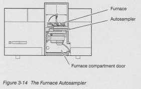
The Fumace Autosampler
Introduction
The autosampler contains all the mechanical and electrical components required to withdraw the correct volume of solution from a selected Container, inject it into the graphite tube, and rinse the pipet tip. Using the autosampler to inject solutions into the graphite tube considerably improves the precision of the analytical results compared to that for manual pipetting. The volumes pipetted and the positioning of the droplet inside the graphite tube are muck more reproducible when performed by the autosampler.
The autosampler fits an the door of the furnace compartment, directly in front of the furnace.
Although you can easily remove it from the door and refft it, this is usually not necessary.
Sampling and Rinsing Pumps
The sampling and rinsing pumps are mounted on the side of the sample table. They are driven by stepping motors to guarantee the precision and accuracy of the selected volumes.
The rinsing pump contains ball valves at the inlet and outlet. The sampling pump contains no valves.
The rinsing System raust be completely filled with liquid to operate correctly.
The rinsing pump delivers a fixed volume of rinsing fluid. The sampling pump delivers the volume that you select in the application program.
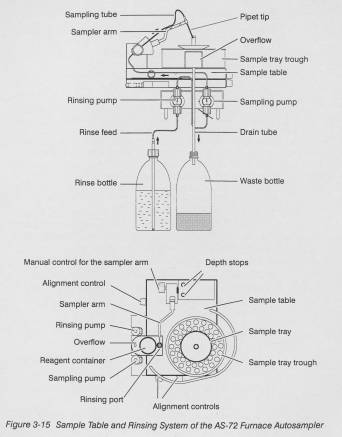
The Sample Table
The sampler arm moves the pipet tip between the pipetting location and the sample injection hole of the graphite tube. The sampler arm is fixed to the sample table. The sample tray trough and the overflow, which contains the rinsing port and the reagent Container, are mounted on a movable plate on the sample table. A stepping motor slews the plate to position the correct reagent or sample Container, or the rinsing port, at the pipetting location.
The sample tray sits in the sample tray trough, which has a plastic cover. The cover protects the samples from contamination and reduces the rate of evaporation of the solvent. You can reduce the rate of evaporation further by pouring a Small volume of water into the sample tray trough.
The sample tray is removable. It is useful to haue several trays so that you can load trays while one tray of samples is being analyzed.
There are two types of sample tray available; with either 80 or 40 locations for samples and reagents.
Sample and Reagent Containers
The sample trays accept sample cups with volumes of 1.2 mL, 2.0 mL or 3.5 mL. Sample cups are available in acid-resistant (polystyrene) or solvent-resistant materials (PTFE, polypropylene, polyethylene).
If you use the 3.5 mL sample cups you raust also use the taller rinsing port supplied with the autosampler.
The sample trays also accept five special 'cloverleaf', 25 mL, Containers which you can use for for reference solutions, modifier solutions or sample solutions for special applications. These Containers are available only in polypropylene.
The overflow has a location for a special 26 mL reagent Container. Use this when you require a larger volume of any reagent. lt has a cover with a small aperture for the pipet tip. These Containers are available in polystyrene, polypropylene and PTFE.
Controlling the Autosampler
With the AA WinLab application you control exactly how and when the solutions will be picked up and injected into the graphite tube. See the online help or the Software Guide for the procedure. For example you can select:
The Order in which the solutions will be picked up.
To pipet some or all of the solutions one alter one another and inject them into the graphite tube together.
To pipet some or all of the solutions separately and inject them separately into the graphite tube.
The Autosampler Operating Cycle
1. The pipet tip is in the rinsing port.
You start the analysis with a software command and the furnace program Starts.
2. The rinsing pump performs three cycles, rinsing the pipet tip with 4.5 mL of rinse fluid.
3. The sampler arm rises and the movable plate positions the requested solution at the pipetting location.
Simultaneously, the sampling pump draws a 15 µL bubble of air into the pipet tip to separate the rinsing liquid from the solution being pipetted.
4. The sampler arm lowers the pipet tip into the solution and the sampling pump sucks the selected volume of solution into the tip. The sampler arm rises.
5. If you selected to pipet more than one solution in one step:
The Container with the next solution is brought to the pipetting location.
A 15 µL bubble of air is drawn into the pipet tip.
Step 4 is repeated for this solution.
Step 5 is repeated until all the solutions you selected have been sucked into the pipet tip.
6. The sampler arm swings over to the graphite furnace and injects the solutions into the graphite tube.
7. The sampler arm swings back to the sample fable and simultaneously the movable plate positions the rinsing port at the pipetting location. The rinsing pump rinnen the pipet tip with rinne fluid.
8. Stegs 3 to 7 are repeated for each step of the analysis pro-gram that requires solutions to be pipetted.
9. When all the solutions have been injected into the graphite tube, the sampler arm returns to the starr position with the pipet tip in the rinsing port.
10. The furnace program continues to the end and the analyte concentration is determined.
11. The preceding steps are carried out for each replicate of every sample and reference solution that you specified.
12. The sample trag rotates to the starting location.
Signal Measurement
Source Intensity Measurement
The spectrometer has an AC modulated single path optical Layout.
To distinguish between the radiation coming from the source and that coming from the atomizer, the spectrometer switches the source an and off rapidly to produce dark and light phases. The light phases are longer than the dark phases.
During the light phase, the spectrometer measures the radiation intensity from the source and atomizer. During the dark phase, it measures only the radiation intensity from the atomizer. From these values the system computes the intensity of the source radiation.
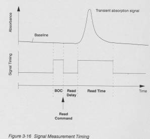
Baseline Offset Correction (BOC)
The spectrometer continuously monitors the intensity of the radiation passing through the system and stores the values from the previous few seconds.
When a read command is given, the system computes the difference between the intensity values for the first and last seconds of the BOC time.
If the difference is less than 0.005 absorbance units, the system computes the mean of the values for the BOC time and uses this as the baseline value.
If the difference is greater than 0.005 absorbance units, the system assumes that absorption has occurred and that the baseline is not stable. It produces an error message.
The BOC time is two seconds. In the furnace program, the length of the step before the Read step raust be at least two seconds, to allow the system to make the BOC measurement.
Timing Procedure for Signal Measurement
Signal Measurement Stages
The relationship between the individual stages of the signal measurement procedure is shown below.
You can alter the Read Delay and Read Time an the Instrument page of the method; see the online help or the Software Guide.
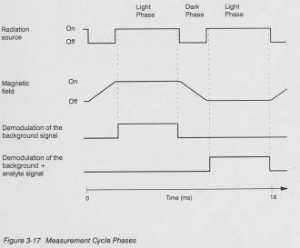
Measurement Cycle Phases Within the Read Time
For the duration of the selected Read Time, the spectrometer repeatedly carries out the 18 ms measurement cycle. The relationship between the various phases of the measurement cycle is shown below. The magnetic field is part of the Zeeman-effect background correction System. This is described in the next section.
Zeeman-Effect Background Correction
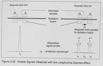
The SIMAA 6000 spectrometer uses the inverse, longitudinal Zeeman-effect to correct the analyte Signal for background attenuation. In this context 'inverse" means that the magnetic field acts on the atomized Sample in the graphite tube and `longitudinal" means that the magnetic field is aligned parallel to the radiation beam. The Zeeman-effect is described briefly below.
The Zeeman Effect
Simple Zeeman Spectra
The Zeeman-effect refers to the splitting of atomic spectral lines into three or more components when the emitting or absorbing species are subjected to a magnetic field. The extra lines arise through the splitting of electron energy levels within the atoms. In the simplest case this splitting produces two extra spectral lines, the cr, and a- components, at each side of a nonshifted live, the n component. The magnitude of the shift depends on the strength of the magnetic field.
The SIMAA 6000 furnace uses a magnetic field strength of approximately 0.8 tesla. This shifts the a+ and a- components by approximately 0.01 nm to each side of the πcomponent.
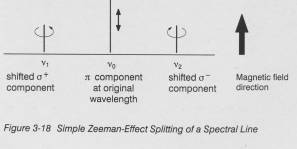
The πcomponent is linearly polarized, with the electric vector (polarization direction) parallel to the magnetic field.
The two shifted lines (c components) are circularly polarized, in opposite directions, with the axes of polarization parallel to the magnetic field.
The different intensities of the lines (the nonshifted live has twice the intensity of the shifted lines) is due to quantum selection rules governing the probability of transitions between the energy levels available to the electrons.
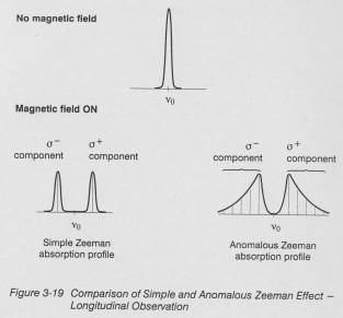
Complex Zeeman Spectra
The brief description given above is for the simplest rase of the Zeeman effect for a singlet spectral line.
For many atoms, the actual relationship between the shifted and nonshifted lines is rauch more complicated and produces complex or anomalous Zeeman Splitting patterns. In these, the ci and n lines can each be Split into many components, but the basic principle of the Zeeman-effect still explains these phenomena.
Applying the Zeeman-Effect Background Correction
Two methods of observing and using the Zeeman-effect are usually used:
The longitudinal configuration where the magnetic field and radiation beam are parallel. This system is used in the SIMAA 6000 spectrometer.
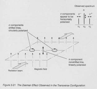
The transverse configuration where the magnetic field and radiation beam are perpendicular to each other. This system is described for comparison.
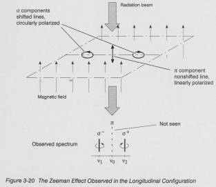
Longitudinal Configuration
This System is used in the SIMAA 6000 spectrometer.
In this arrangement only the two shifted lines are seen.
These appear to be (and are) circularly polarized, because of the direction of viewing which is parallel to the axis of circular polarization.
The nonshifted live cannot be seen because its electric vector is aligned wich the radiation beam (an electromagnetic wave does not propagate in the direction of its electric vector).
With the longitudinal configuration no polarizer is needed.
Transverse Configuration
With this arrangement, the nonshifted live and the two shifted lines are seen.
The shifted lines appear to be linearly polarized (although in fact they are circularly polarized) because of the direction of viewing, which is perpendicular to the axis of the circular polarization. A polarizer in the optical System is needed to use the transverse configuration for background correction.
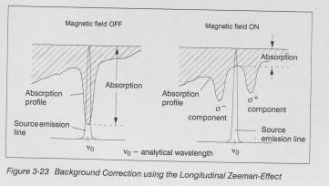
Analyte Signals and Background Correction
Each measurement cycle contains two light phases as shown in Figure 3-17, page 3-36. The magnetic field is on during one of them and off during the other.
With the magnetic field on, the analyte signal is Split into the two shifted a components and the 'unseen" nonshifted i component. The two a components cannot absorb energy at the analytical wavelength, and the n component, not having an effect in the longitudinal direction, also cannot absorb energy at the analytical wavelength.
Any attenuation of radiation at the analytical wavelength is thus due only to the background (structured and/or continuous).
With the magnetic field off, any attenuation of radiation at the analytical wavelength is due to absorption by the single analyte signal in addition to any attenuation due to the background (structured and/or continuous).
This procedure of rapidly alternating measurements of [analyte+background] and [background only], at exactly the saure wavelength during the measurement cycle gives the System its ideal double-beam characteristics.
Technical Data
Spectrometer
Principle
Atomic absorption spectrometer, specially designed for simulta‑
neous multi-element graphite furnace analyses.
Computer controlled, using special application program running under a decktop graphic software.
Double-beam measurement system with automatic baseline Offset correction BOC.
AC modulated live source and magnetic field (for the background correction system).
Single path, all-reflecting optical system. Front-surfaced optics protected by a silica coating.
Polychromator
Echelle polychromator in a tetrahedral configuration. Monochromator Operation with software controlled wavelength selection.
Grating:
Ruled area: 143 mm x 47 mm, 79 lines/mm
Blaze angle: 63.4 °
Prism: Fused quartz, 21.15°
Focal length: 500 mm
Slits: main: 2.3 mm
Cross: 1.0 mm
Wavelength range; 190 to 860 nm
Spectral bandpass: 0.2 nm at 200 nm
Reciprocal linear dispersion:
at 200 nm: 0.1 nm/mm
at 800 nm: 0.4 nm/mm
Detector
Solid-state, two-dimensional diode array, 60 diodes.
Lamps
Line sources. Up to four, coded, single-element or multi-element hollow cathode (HCL) or electrodeless discharge lamps (EDL).
Background correction
Inverse longitudinal Zeeman-effect.
Atomization
Transversely heated graphite furnace, electrically heated.
Signal handling
Peak Height.
Peak Area non time-averaged Integration.
Linear in absorbance and concentration. Measurement ranges:
Absorbance: 0.5 to 2.000
concentration: 0.0001 to 9999 concentration units
Expansion factor: 0.01 to 100
Read time: 1 to 60 seconds
Read delay: 0 to 60 seconds
Automatic averaging of up to 99 readings.
Automatic calculation of the mean, standard deviation and relative standard deviation.
Automatic baseline Offset correction, BOC.
Calibration
Automatic zeroing, resloping and recalibration. Calibration/recalibration using up to 15 calibration solutions. Calibration coefficients determined by a least squares procedure.
Analytical Curve Technique:
Linear wich zero or non-zero intercept.
Non-linear, 2-coefficient or 3-coefficient, zero or non-zero intercept.
The System can choose the most suitable of the above equations after measuring the
calibration solutions.
Bracketing calibration.
Analyte addition technique
Zero or non-zero intercept.
Additions calibrate (zero intercept).
Computer
PC with 486 processor, Microsoft Windows 3.1.
8 MB RAM.
200 MB hard disk.
Floppy drive, 31/2- 1.44 MB.
One IEEE-488 interface, one eherner interface.
Interfaces for a mouse and printer.
GPIB, IEEE-488 interface board.
VGA color graphics board and compatible monitor. compatible mouse and appropriate connecting cable.
The IEEE-488 interface board and connecting cable are supplied with the spectrometer Software.
For data Jogging, a suitable printer is required.
Application program
Special application program AA WinLab.
On-line help function.
Hard disk or floppy storage of measurement data, signals and complete analytical methods, for single- and multi-element analyses.
Special Reporter, Reformatter and Library Manager applications for producing data reports and reformatting data for importing into other data handling programs.
Graphics
High resolution display of the signals from the graphite furnace. Simultaneous display of the corrected analyte signal and the background signal.
Calibration curve display; newest + previous if a reslope or recalibration dope.
Storage and recall of transient absorbance signals.
Hard copy printout of screen graphics on an associated printer. In continuous mode; printout of real time signals on an associated printer.
Interfaces
IEEE-488 interface.
Ethernet interface.
Instrument interface for Service purposes.
Power requirements
230/400 V, 3-phase, 50/60 Hz,
power consumption 5000 VA,
or
208-240 V, 50/60 Hz, (2 pole - 3 wire - grounding)
power consumption 5000 VA.
The spectrometer is supplied with a suitable power supply connector.
either a 5 pole CENELEC connector (IEC 309-2:89 + Corrigendum 1992) rated for 32 A (3 phases + neutral + protective earth); or a 3 pole NEMA L6-30P twistlock connector, rated for 250 V I
30 A, (2 pole - 3 wire - grounding; type 2 phases + protective earth).
Electrical protection
Insulation: Class: I
Installation Category (Overvoltage Category): 11 Pollution Degree: 2
In compliance with IEC 1010.
Safety and EMC standards
IEC 1010-1: 1990+A1, modified; EN 61010-1-1993; VDE 0411 EMC part 1/03.94.
EMC (Electromagnetic compatibility)
EN 55011:91, DIN VDE 0875 part 11/07.92 for emission. EN 50082-1:92, VDE 0839 part 82-1/03.93 for immunity.
Environmental requirements
+15 °C to +35 °C
20-80 % relative humidity; non-condensing.
Dimensions
Width: 1050 mm, with handles: 1190 mm
Height: 675 mm
Depth: 705 mm, with autosampler: 950 mm
with handles: 725 mm
Mass (Weight)
Spectrometer (without Computer)
210 kg, 462 lb without autosampler,
216 kg, 475 lb with autosampler.
Zeeman Fumace
Principle
Transversely heated graphite furnace using the longitudinal Zeeman effect for background correction.
Magnetic field is parallel to the radiation beam, modulated at live supply frequency, and activated only during the measurement cycle.
Magnetic field strength, inside the furnace: approx. 0.8 T.
Temperature range
Room temperature (20 'Q to 2600 'C, programmable in steps
range of 10 'C.
Heating Rate
Programmable up to approx. 2000 'C/s (maximum power heating).
Gas requirements
Inert gas supply required for Operation (not provided); argon recommended.
A second, special gas can also be used.
Automatic gas shutdown when the furnace has been idle for 10 minutes.
Pressure: 350 kPa (3.5 bar 51.0 psi) ±10 %
Gas flow: max. 700 mL/min
Gas Flows
Programmable internal flow:
2 x 250 mL/min
2 x 50 mL/min
0 mL/min
External flow: 2 x 100 mL/min, fixed.
Cooling
Recirculating cooling system, see page 3-52 for the technical data.
Automatic shutdown of the cooling system when the furnace has been idle for 10 minutes.
Fume extraction unit
Takes fumes from directly above the Sample injection hole of the graphite tube. This raust be used in addition to the main fume ventilation system.
Furnace program
Up to twelve independent steps.
Parameters:
Isothermal temperature holding time: 0-99 s, in steps of 1 s.
Isothermal temperature: 20-2600 'C in steps of 10 °C
Heating rate: programmable, time dependent or Maximum power.
Internal gas flow
Read delay
Read time
Magnetic field is automatically activated by the system at the correct time.
Safety features
Automatic circuit breaker should the furnace Start drawing too muck current.
Safety lock to prevent operation with the furnace open or with a defective tube.
Protection against overheating of the furnace, transformer, or Magnet.
Safety lock to prevent operation with low gas pressure. Automatic Software Checks for program errors and data transfer errors.
Power Requirements
Integrated into spectrometer; see technical date for spectrometer.
Dimensions
Integrated into spectrometer; see technical date for spectrometer.
Mass (Weight)
Integrated into spectrometer; see technical date for spectrometer.
AS-72 Autosampler
Principie
Random access furnace autosampler with programmable sampling volume. Can combine and dilute solutions automatically in the graphite tube and produce calibration solutions from stock solutions.
Control
From the spectrometer's application program.
Sample Tray
Removable trays with 40 or 80 locations.
The sample table has an additional location for a 26 mL Container.
80-location tray:
75 locations for 1.2 mL sample cups;
5 locations (76-80) for 2.0 mL or 3.5 mL sample cups, or special 25 mL cloverleaf form containers (20 mL usable).
40-location tray:
35 locations for 2.0 or 3.5 mL sample cups;
5 locations (36-40) for 2.0 mL or 3.5 mL sample cups, or special 25 mL cloverleaf form containers (20 mL usable)
Rinsing
A rinsing port is integrated into the sample table. This rinses the inside and outside of the pipet tip.
Rinse volume 1.4 mL per cycle; fixed. Number of cycles programmable.
Chemical Resistance
Rinse feed tubes: FEP, PTFE
Rinse bottle: PE, PTFE*
Waste bottle: PE, PTFE*
Drain tube: PVC
Sample cups and containers: PS, PP, PE*, PTFE* Sampling tube, pipet tip: PTFE
Pumps: inert, fluorinated engineering plastic.
* Optional
Minimum required sample volume
Minimum: 0.1 mL, maximum: volume of Container.
Pipetted volume
Minimum: 0.1 µL, maximum: 99 µL.
For best precision a minimum of 5µL is recommended. Maximum = volume of one solution or sum of individual solution volumes pipetted together; i.e.
[sample + reference solution + matrix modifiers + diluent]
Power supply
From spectrometer or furnace power unit.
Dimensions
Width: 280 mm
Height: 200 mm
Depth: 450 mm
Mass (Weight)
Approx. 6 kg, 13.2 lb.
Cooling System
Principle
Self-priming recirculating system with fan-assisted hegt exchanger.
Coolant
1:10 mixture of glycerine in deionized water or Sediment-free drinking water.
Volume
Approx. 5 L
Water temperature
Output: 36°C ±5 °C
Inlet max: 90°C
Fan cut in temp: 40°C
Flow
2.5 L/min
Air flow
Approx. 400 m3/hour
Water pressure
300 kPa, (3 bar, 43.5 psi)
Connections
Reinforced hose, Ld. 8 mm; automatic connectors with integral shut off valves.
Power requiremets
230 V, 50/60 Hz, supplied by the spectrometer.
Power consumption: approx. 140 VA
Dimensions
Width: 200 mm
Height: 375 mm
Depth: 500 mm
Mass (Weight)
Approx. 18 kg, 40 lb with coolant.
Votre Labexchange-équipe sera heureux de vous aider:

Christian Schmid
Laboratoire et analyse, Équipment de laboratoire, Life science

Hubert Sauter
Spectroscopie, Chromatographie


