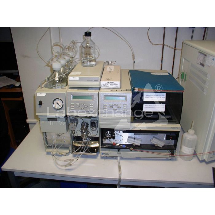
Thermo LCQ DECA
| Objektnummer | B00018595 |
|---|---|
| ID-number | 018595 |
| Object name | Thermo LCQ DECA |
| Status | Stock unit |
Product group: LC / MS
Status, terms of delivery and payment
Verification of devices
The second-hand devices are verified by Labexchange Service GmbH before delivery. You are receiving only fully functional devices.
Dispatch time
The stated dispatch times are the shortest possible ones for each article. The effective dispatch times can vary. The effective dispatch times will be stated in the order confirmation.
As a matter of principle, we are offering collective deliveries. The shipping time is calculated based on the position with the longest lead time. A partial delivery is possible on explicit request.
Shipping methods
Parcel services, forwarding agencies, self-pickup, delivery by Labexchange fleet.
Delivery information
Prices exclude shipping costs. Stated shipping costs are to be expected. Deviations are possible. If transport costs are not specified, please ask separately for them.
The stated transport and packing charges apply to the most favorable route if transport and are to be understood as subject to verification due to unexpected cost increases. By reason of unpredictable events, cargo rates and delivery times can change at any time and therefore have to be adapted to the recent situation. Import formalities and possible customs charges will be borne by the purchaser. Incoterm coding according to Incoterms 2010: For persons who collect the devices themselves: EXW, for dipatch by sea: CFR, by air freight: CPT, other shipments: DAP. Note for international shipments: A proof of preference/EUR1 will not be issued by us. When self-collecting/ordering EXW from countries within or outside the European Union, 16% VAT will be retained as a deposit until we have received the corresponding confirmation of arrival/bill of delivery from the buyer.
Terms of payment
We do not accept payment by letter of credit, PayPal, etc. In each case the invoice amount is payable without deduction. Discount is not granted.
|
Country |
Possible payment methods |
Comment |
|
DE, AT, CH |
Payment by invoice, payment in advance, paymet by credit card |
Payment by invoice is only possible for corporate clients. |
|
NL, BE, LU |
Payment by invoice, payment in advance, payment by credit card |
Payment by invoice is only possible for corporate clients |
|
Other countries |
Payment in advance, payment by credit card |
|
Our General Terms of Sale, Delivery and Payment are valid and are available for download here.
The goods are offered subject to prior sale.
Definition of status
All articles are used articles, except an article is listed especially as a new device.
|
Status |
Condition |
Comment |
|
Immediately available |
Used | The article is fully functional and in impeccable condition. It can be shipped immediately. |
| In stock |
Used |
The article is on stock. Our service technicians will verify the article before delivery. You are receiving only a fully functional article. |
|
Published |
Used |
The article is still with the provider. After your order the article will be purchased and verified by us before being shipped to you. A certificate of operativeness as well as a service report are included in delivery. |
|
New device |
new |
The article is brand new and unused. Regarding new equipment the guarantee/warranty conditions of the corresponding manufacturer apply. |
|
Labprocure |
Used |
Labprocure GmbH, as the advertiser, is responsible for the content of this device offer. Labprocure assumes liability for the offers advertised here and for the photos and offer texts included. Labprocure GmbH, Bruckstraße 58, 72393 Burladingen. |
The following illustrations and descriptions are referring to the instrument model and are drawn from brochures. They are not representing the delivery volume. The exact delivery content you will find only in the offering text.
API Source
The atmospheric pressure ionization (API) source forms gas phase sample ions from sample molecules that are contained in solution. The API source also serves as the sample interface between the LC and the MS detector. You can operate the API source in either the electrospray ionization (ESI) or atmospheric pressure chemical ionization (APCI) mode.
The API source consists of two assemblies:
API probe assembly (ESI or APCI)
API stack
API Probe Assembly
The API probe assembly is the portion of the API source that is external to the vacuum manifold. You can change the ionization mode of the MS detector and switch the probe assemblies without breaking the vacuum. Two API probe assemblies are available with the LCQDECA:
ESI probe assembly
APCI probe assembly
ESI Probe Assembly
The ESI probe assembly consists of the ESI flange and the ESI probe. See Figure 1-1. The ESI flange holds the ESI probe in position next to the entrance of the heated capillary, which is part of the API stack. The ESI flange also seals the atmospheric pressure region of the API source. In addition, when it is in the operating Position against the spray shield, the ESI flange compresses the high-voltage safety-interlock switch. The ESI flange mounts an rails that allow movement of the flange toward and away from the vacuum manifold for easy servicing. Two flange retainer bolts hold the flange in place against the spray shield of the API stack. A grounded fltting holder secures a stainless steel grounded fitting that connects the sample transfer line to the PEEK safety sleeve and fused-silica sample tube.
The ESI probe produces charged aerosol droplets that contain sample ions. The ESI probe accommodates liquid flows of 1 µL/min to 1 mL/min without splitting.
The ESI probe includes the ESI fused-silica sample tube and PEEK safety sleeve, needle, nozzle, and manifold. Sample and solvent enter the ESI probe through the fused-silica sample tube. The sample tube is a short section of 0.1 mm ID fused-silica capillary that extends from a Fingertight fitting and ferrule secured to the grounded fitting holder, through the sample inlet and into the ESI needle, to within 1 mm from the end of the ESI needle. The ESI needle, to which a large negative or positive voltage is applied (typically ±4.5 to ±5 kV), sprays the sample solution into a fine mist of charged droplets. The ESI nozzle directs the flow of sheath gas and auxiliary gas at the droplets. The ESI manifold houses the ESI nozzle and needle and includes the sheath gas, auxiliary gas, and sheath liquid plumbing. The sheath gas plumbing and auxiliary gas plumbing deliver dry nitrogen gas to the nozzle. The sheath liquid plumbing delivers sheath liquid to the nozzle.
The ESI probe has inlets for the introduction of sample solution, sheath gas, auxiliary gas, and sheath liquid into the API source. The sheath gas is an inner coaxial nitrogen gas that sprays (nebulizes) the sample solution into a fine mist as it exits the sample tube. Typical sheath gas flow rates for ESI are 20 to 40 psi for sample flow rates of 5 to 10 µL/min and 80 units for sample flow rates of 200 to 1000 µ/min. When you tune the LCQDECA, you may need to adjust the sheath gas flow rate until the ion signal is stable.
The auxiliary gas is an outer coaxial nitrogen gas that assists the sheath gas in the nebulization and evaporation of sample solutions. The auxiliary gas also helps lower the humidity in the ion source. Typical auxiliary gas flow rates for ESI are 10 to 20 units. Auxiliary gas is usually not needed for sample flow rates below 100 mL/min. Refer to Table 1-1 for specific guidelines for LC/ESI/MS operation.
The sheath liquid is a solvent used to stabilize and enhance the ESI process for some solution chemistries (for example, high aqueous content) that do not readily form an electrospray and to provide make-up solvent in CE and CEC applications. Sheath liquid is injected by the syringe pump and exits the nozzle coaxially to the sample tube.


Table 1-1. Guidelines for LC/ESI/MS Opteration
|
LC Flow Rates |
Suggested Column Size |
Probe Position (1 to 4) |
Heated Capillary Temperature |
Sheath Gas |
Auxiliary Gas |
|
Infusion or LC at flow rates of <10 µL/min |
Capillary |
2 |
Typical setting: 150 to 275 °C |
Required Typical setting: 20 to 40 units |
Not required Typical setting: 0 units |
|
LC at flow rates from 50 to 100 µL/min |
1 mm ID |
2 |
Typical setting: 350 °C |
Required Typical setting: 80+ units |
Not required, but might heip depending on conditions |
|
LC at flow rates from 200 to 500 µL/min |
2 to 3 mm ID |
3 |
Typical setting: 350 °C |
Required Typical setting: 80+ units |
Not required, but usually helps to reduce solvent background ions Typical setting: 20 units |
|
LC at flow rates from 0.5 to 1 mL/min |
4.6 mm ID |
3-4 |
Typical setting: 350 °C |
Required Typical setting: 80 to 100 units |
Required Typical setting: 20 units |
|
Note. In negative ion mode, waveform 2 might be required (depending on solvents and modifiers used). In positive ion mode with flow rates of >400 µL/min, waveform 2 might be required. |
|||||
APCI Probe Assembly
The APCI probe and flange assembly is a single molding including the corona discharge needle assembly. See Figure 1-2. The APCI flange holds the APCI probe and the corona discharge needle assembly in position next to the entrance of the heated capillary. As with the ESI flange, the APCI flange seals the atmospheric pressure region (also called the spray chamber) of the API source. The APCI flange mounts on rails that allow movement of the flange toward and away from the vacuum manifold for easy servicing. Two flange retainer bolts hold the flange in place against the spray shield of the API stack. When the APCI flange is in the operating position against the spray shield, it compresses the high-voltage safety-interlock switch.
The APCI probe ionizes the Sample by atmospheric pressure chemical ionization. The APCI probe accommodates liquid flows of 100 pL/min to 2 mL/min without splitting.
The APCI probe includes the APCI sample tube, nozzle, sheath gas and auxiliary gas plumbing, and vaporizer. Sample and solvent enter the APCI nozzle through the sample tube. The sample tube is a short section of 0.15 mm ID fused silica tubing that extends from the sample inlet to 1 mm past the end of the nozzle. The manifold houses the APCI nozzle and includes the sheath gas and auxiliary gas plumbing. The APCI nozzle sprays the sample solution into a fine mist. The sheath gas and auxiliary gas plumbing deliver dry nitrogen gas to the nozzle. Typical sheath gas flow rates for APCI are 60 units for sample flow rates of 100 µL/min, 80 units for sample flow rates of 1 mL/min, and 85 units for sample flow rates of 2 mL/min. Typical auxiliary gas flow rates for APCI are 10 to 20 units. The droplets in the mist then enter the vaporizer. The vaporizer flash vaporizes the droplets at temperatures up to 600 °C. Typical vaporizer temperatures are 450 to 550 °C for most flow rates. Refer to Table 1-2 for specific guidelines for LC/APCl/MS Operation.
Table 1-2. Guidelines for LC/APCI/MS Operation
|
LC Flow Rate |
Heated Capillary Temperature |
Vaporizer Temperature |
Sheath Gas |
Auxiliary Gas |
|
LC at flow rates from 0.2 to 2 mL/min |
Typical setting: 150 to 225 °C |
Typical setting: 400 to 550 °C |
Required Typical setting: 50 to 100 units |
Not required, but usually helps to reduce solvent background ions Typical setting: 0 to 20 units |
The sample vapor is swept toward the corona discharge needle by the flow of the sheath and auxiliary gasses. The corona discharge needle assembly is mounted an the APCI flange. The assembly positions the tip of the corona discharge needle near the vaporizer. A high potential (typically ±3 to ±5 kV) is applied to the corona discharge needle to produce a corona discharge current of up to 10 µA. (A typical value of the corona discharge current is 5 µA.) The corona discharge from the needle produces a reagent ion plasma primarily from the solvent vapor. The sample vapor is ionized by ion-molecule reactions with the reagent ions in the plasma. APCI requires a constant source of electrons for the ionization process. Thus, the corona discharge current is set and regulated. The potential applied to the corona discharge needle varies, as needed, to provide the required current.

Your Labexchange-Team will gladly help:

Christian Schmid
Laboratory and analysis, Laboratory equipment, Life science

Hubert Sauter
Spectroscopy, Chromatography


